Finite difference design method of magnatic resonance imaging (MRI) system gradient coil

A gradient coil, finite difference technology, applied in computing, special data processing applications, instruments, etc., can solve the problem of time-consuming optimization process

Inactive Publication Date: 2011-03-30
ZHEJIANG UNIV
View PDF2 Cites 26 Cited by
  • Summary
  • Abstract
  • Description
  • Claims
  • Application Information

AI Technical Summary

Problems solved by technology

This method is relatively straightforward and easy to i

Method used


Image

  • Finite difference design method of magnatic resonance imaging (MRI) system gradient coil
  • Finite difference design method of magnatic resonance imaging (MRI) system gradient coil
  • Finite difference design method of magnatic resonance imaging (MRI) system gradient coil

Examples


Embodiment Construction

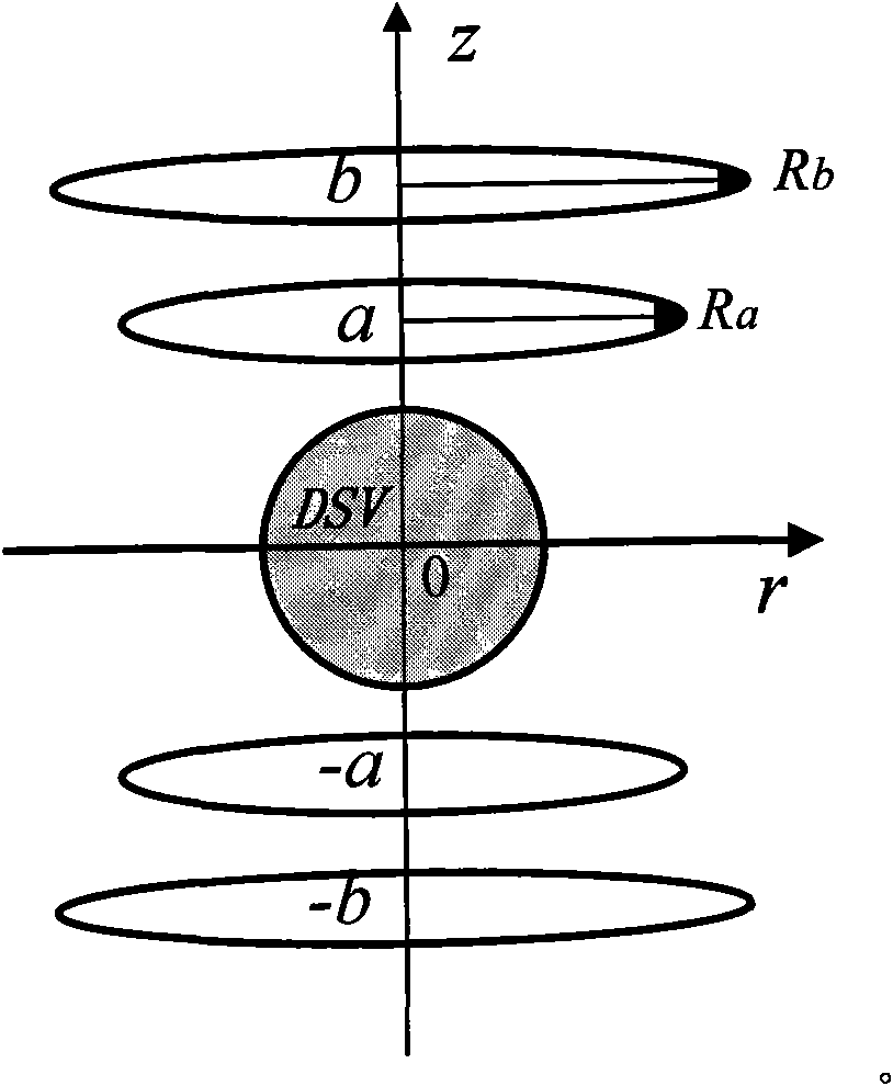
[0021] The method of the present invention is described below by taking the design of the biplane X gradient coil in an open MRI system as an example, and the present invention is applicable to the design of a gradient coil system of any structure.

[0022] figure 1 Shown is the configuration diagram of the dual-plane X-gradient coil, the coils are distributed on a disc with the z-axis as the central axis and symmetrical about the z=0 plane, and the imaging region of interest is distributed on the central sphere with the origin as the center superior. In this embodiment, the target gradient field strength of the imaging region of interest is required to be G x =6.25mT / m, the sphere diameter DSV (diameter of spherical volume) is required to be 0.38m, the two main coil disks are located at z=a and z=-a, the distance is 2a=0.5m, and the coil size is limited to the radius R a In a circle of =0.43m, two shielding coil disks are located at z=b and z=-b, the distance is 2b=0.7m, an...


PUM


Abstract

The invention discloses a finite difference design method of a magnatic resonance imaging (MRI) system gradient coil, which comprises the following steps: firstly, dividing finite difference grids in the coil space, and establishing finite difference relation between a node stream function and grid current density on each grid node; subsequently, selecting a constraint field point in the magnetic field related region of the MRI system gradient coil, and computing the magnetic induction intensity on the constraint field point according to the design requirements; then, establishing a system of linear equations between the node stream function and the magnetic induction intensity of the constraint field point according to the Biot-Savart law; simultaneously, establishing a penalty function of the system of linear equations according to the actual engineering requirements; and finally, solving the system of linear equations by a method of regularization to acquire a node stream function value, and determining the current style of the coil by a constant stream function line. The invention is simple and effective and can be suitable for designing gradient coil systems in any structure.

Description

technical field [0001] The invention relates to a finite difference design method of a gradient coil in a magnetic resonance imaging (abbreviated as MRI) system. Background technique [0002] In the field of magnetic resonance imaging, a great deal of work has been done with respect to gradient coils in order to obtain uniform gradient magnetic fields. There are mainly two design methods. One is a method based on discrete wire space, such as simulated annealing (S.Crozier and D.M.Doddrell, "Gradient-coil design by simulated annealing," J.Magn.Reson.A, vol.103, pp.354-357, 1993 .); the other is a design method based on continuous current density space, such as the target field method (R.Turner, "A target field approach to optimal coil design," Journal of Physics D: Applied Physics, vol.19, pp.L147 -L151, 1986.); The above two methods have their own advantages and disadvantages. [0003] Based on the method of discrete wire space, the current-carrying element (ring or arc) ...

Claims


Application Information

Patent Timeline
IPC IPC(8): G06F17/50
Inventor 夏灵朱敏华刘锋
Owner ZHEJIANG UNIV
Why Eureka
Try Eureka