Tower ground wire universal lifting mechanism

A lifter and ground wire technology, applied in the direction of overhead lines/cable equipment, etc., can solve the problems of low work efficiency, difficult installation of wire clips, long power failure time, etc., to improve work efficiency, facilitate high-altitude operations, and improve working conditions. Effect

Inactive Publication Date: 2011-03-30
ZHUMADIAN POWER SUPPLY ELECTRIC POWER OFHENAN
View PDF6 Cites 6 Cited by
  • Summary
  • Abstract
  • Description
  • Claims
  • Application Information

AI Technical Summary

Problems solved by technology

In the work of newly building and replacing the ground wire clips of transmission lines, there are problems such as inappropriate tools, no special tools, and difficult installation of wire clips; it seriously affects the installation of the ground wires of transmission lines, making the construction period overdue, and the ground wire clips are in installation. Due to the closeness between the ground wire and the hanging point, the current lifting method takes 60 minutes, which not only has low work efficiency, high labor intensity, but also causes long power outages, which affects the reliability of power supply
[0003] This method often causes shoulder pain, redness and swelling of the installer, and at the same time greatly increases the stress on the foot buckle, which far exceeds the test load of the foot buckle. Once the foot buckle is damaged, the consequences will be disastrous. Some comrades use some unconventional method, causing certain hidden dangers to safe and civilized production and the life safety of employees

Method used


Image

  • Tower ground wire universal lifting mechanism
  • Tower ground wire universal lifting mechanism
  • Tower ground wire universal lifting mechanism

Examples


Embodiment 1

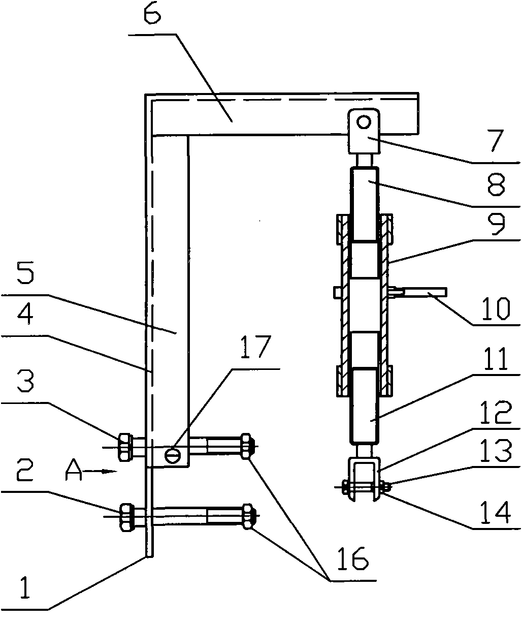
[0017] Depend on figure 1 , figure 2 The shown universal lifter for a tower ground wire includes a vertically arranged lifting rod 9, a fixed bracket, an upper connecting rod and a lower connecting rod. A handle 10 is horizontally provided on the outer surface of the middle part of the lifting rod 9, and the upper connecting rod includes the stud part 8 of the joint 7 fixed on the top, and the lower connecting rod includes the stud part 11 of the terminal provided at the bottom; The column part 8 is assembled in the upper end of the lifting rod 9, the stud part 11 of the lower connecting rod is assembled in the lower end of the lifting rod 9, and the screw threads of the two stud parts 9, 11 of the upper and lower connecting rods are in opposite directions. The fixed support includes a column and a cross bar 6 fixed on the top of the column, and the joint 7 is hinged at the end of the cross bar 6 . The column and the cross bar 6 are all angle irons, and the angle irons are ...

Embodiment 2

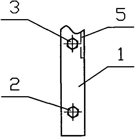
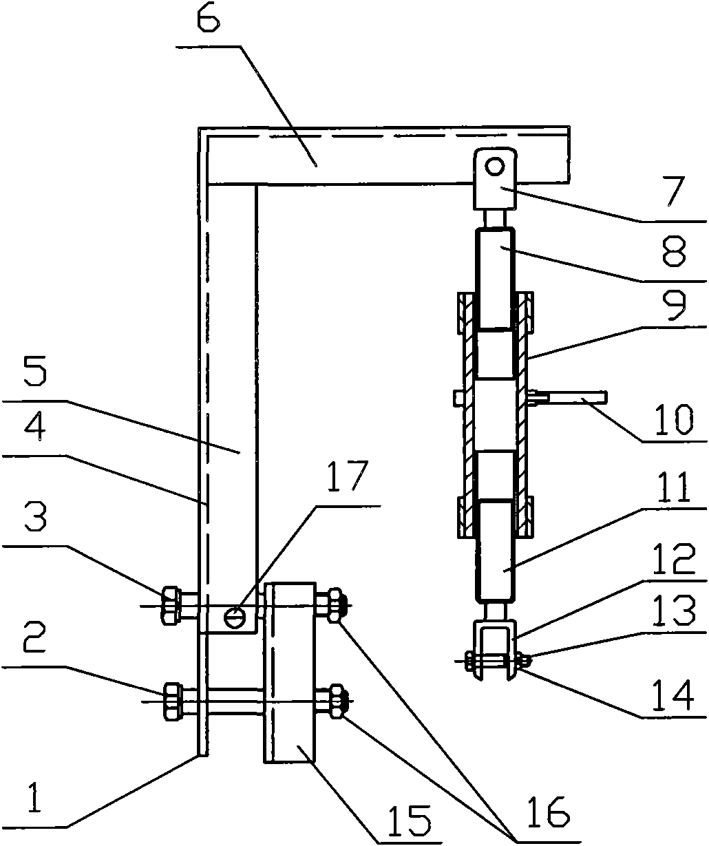
[0020] Depend on image 3 The difference between the universal riser for pole tower ground wire shown in Embodiment 1 is that it includes an auxiliary reinforcing iron 15 arranged on the side of the extension part 1, and the auxiliary reinforcing iron 15 is provided with upper and lower fixing holes. Corresponding to the two fixing holes respectively, the two bolts 3 and 2 are inserted through the auxiliary reinforcement iron 15 and the extension part 1 vertically and horizontally respectively, and the ends of the bolts 3 and 2 are provided with nuts 16 . The auxiliary reinforcing iron 15 is also an angle iron, and the fixing hole is arranged on a vertical surface of the angle iron of the auxiliary reinforcing iron 15 .

[0021] This embodiment is used when the fixed bracket is stressed, and the auxiliary reinforcing iron 15 can increase the bending and tensile strength and improve the safety factor.


PUM


Abstract

The invention discloses a tower ground wire lifting mechanism, comprising a lifting rod vertically arranged, the lifting rod is provided with a handle, the upper part of the lifting rod is connected with an upper connecting rod by a screw thread, the lower part of the lifting rod is connected with a lower connecting rod by a screw thread, the screw thread turning directions of the upper and lower connecting rods are reverse, the lower connecting rod is provided with a connector lug, and the upper connecting rod is connected with a fixed support. The invention is a special tower ground wire lifting mechanism applicable to iron tower and cement pole.

Description

technical field [0001] The invention relates to the technical field of electrical appliances, in particular to a universal riser for tower ground wires. Background technique [0002] At present, the ground wire of the transmission line has problems such as serious corrosion and aging equipment, and needs to be replaced. In the work of newly building and replacing the ground wire clips of transmission lines, there are problems such as inappropriate tools, no special tools, and difficult installation of wire clips; it seriously affects the installation of the ground wires of transmission lines, making the construction period overdue, and the ground wire clips are in installation. Due to the closeness of the ground wire and the hanging point, the current lifting method takes 60 minutes, which not only has low work efficiency, high labor intensity, but also causes long power outages, which affects the reliability of power supply. [0003] This method often causes shoulder pain,...

Claims


Application Information

Patent Timeline
Patent Type & Authority Applications(China)
IPC IPC(8): H02G1/02
Inventor 李卫军李强有殷俊河
Owner ZHUMADIAN POWER SUPPLY ELECTRIC POWER OFHENAN
Why Eureka
Try Eureka