
Structure of vertical take-off and landing rotor aircraft

A vertical take-off and landing, aircraft technology, applied in the aviation field, can solve the problems of complex aerodynamics, low hovering efficiency, and inability to take off and land vertically, and achieve uniform aerodynamic load distribution, improved hovering efficiency, and favorable design Effect

Active Publication Date: 2013-08-28
韦斯豪
View PDF3 Cites 0 Cited by
  • Summary
  • Abstract
  • Description
  • Claims
  • Application Information

AI Technical Summary

Problems solved by technology

[0002] Although the helicopters in the prior art can take off and land vertically, their forward flight speed is low and the flight range is short; while fixed-wing aircraft can fly fast and have a long range, but they cannot take off and land vertically, so they cannot hover in the air.
[0003] At present, the existing tilt rotor aircraft can not only take off and land vertically, but also can fly forward at a higher speed and achieve a relatively large range, but its structure is complicated, the tilting mechanism is complicated and reliable, and the technical requirements are high. The aerodynamics of the whole machine are complex and the maneuverability is poor
And because part of the downwash airflow of the rotor is blocked by the wings, the hovering efficiency is low

Method used


Image

  • Structure of vertical take-off and landing rotor aircraft
  • Structure of vertical take-off and landing rotor aircraft
  • Structure of vertical take-off and landing rotor aircraft

Examples


Embodiment Construction

[0019] The present invention is described in further detail below in conjunction with accompanying drawing:

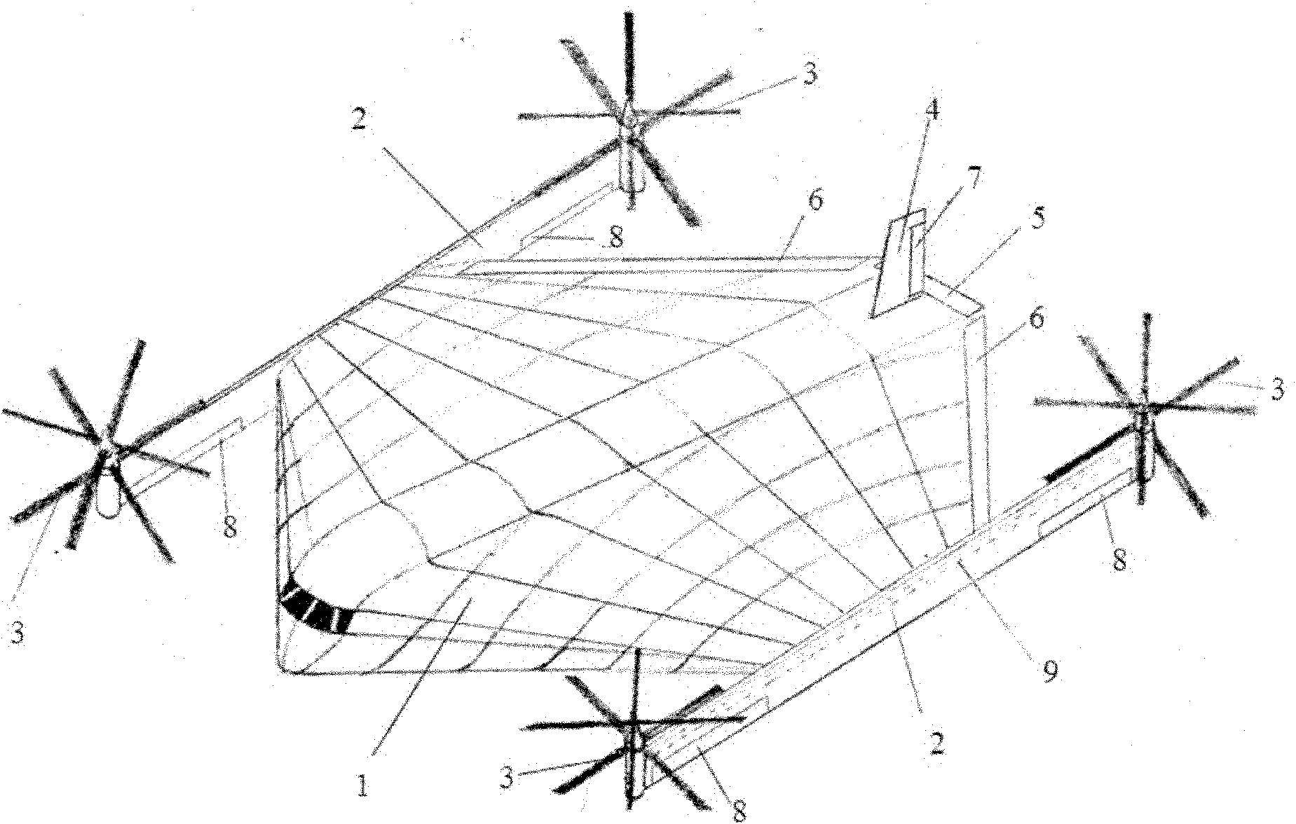
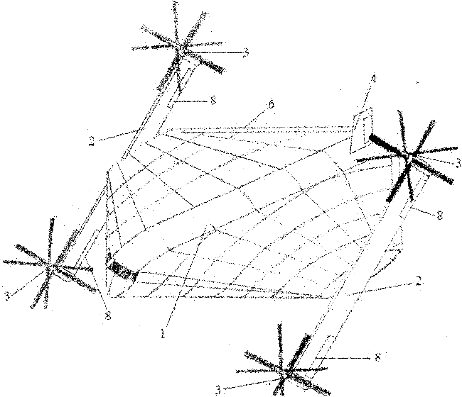
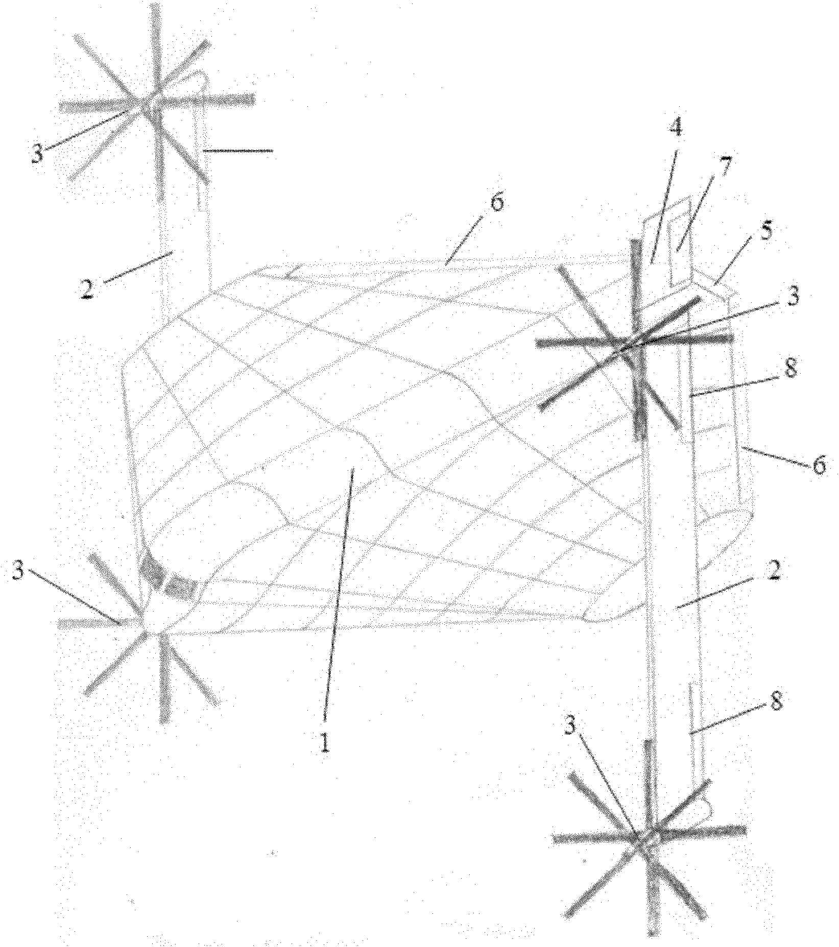
[0020] see figure 1 , figure 2 or image 3 , the vertical take-off and landing rotorcraft structure of the present invention includes a flying-wing fuselage 1 and wings 2 connected to the flying-wing fuselage 1 . Wherein at the rear portion of flying-wing type fuselage 1, be provided with vertical empennage 4, horizontal empennage 5 and flap 6, respectively be provided with an auxiliary wing 2 at the both sides of flying-wing type fuselage 1, as shown in the figure, this aircraft The wing 2 is flat and long, and is connected with the flying wing type fuselage 2 by a tilting mechanism at the middle part of the wing 2 . Both ends of the wing 2 are respectively provided with a rotor system 3 , and a vertically downward rudder 8 is arranged below the rotor system 3 at both ends of the wing 2 .

[0021] figure 1 It is a structural schematic diagram of a preferred embo...


PUM


Abstract

The invention discloses a structure of a vertical take-off and landing rotor aircraft, which comprises a flying wing aircraft body and wings connected with the flying wing aircraft body, wherein the rear part of the flying wing aircraft body is provided with a vertical stabilizer, a horizontal stabilizer and wing flaps; a pair of wings is arranged on each side of the flying wing aircraft body which is flat and long; the middle parts of the wings are connected with the flying wing aircraft body through tilting gears; rotor systems are arranged on the two ends of wings; and rudders are arrangedon the two ends of the wings and below the rotor systems. In the structure of the aircraft, the flying wing aircraft body is combined with the rotor systems, a reasonable design enables the aircraft to take off and land vertically and reaches the flight speed and range of a fixed wing aircraft. The structure is relatively simple.

Description

technical field [0001] The invention belongs to the technical field of aviation, and relates to an aircraft, in particular to a vertical take-off and landing rotor aircraft structure. Background technique [0002] Although the helicopters of the prior art can take off and land vertically, their forward flight speed is low and the flight range is short; although the fixed-wing aircraft has a fast flight speed and a long range, they cannot take off and land vertically, and cannot hover in the air. [0003] At present, the existing tilt rotor aircraft can not only take off and land vertically, but also can fly forward at a higher speed and achieve a relatively large range, but its structure is complicated, the tilting mechanism is complicated and reliable, and the technical requirements are high. The aerodynamics of the whole machine are complicated and the maneuverability is poor. And because part of the downwash airflow of the rotor is blocked by the wings, the hovering effi...

Claims


Application Information

Patent Timeline
Patent Type & Authority Patents(China)
IPC IPC(8): B64C27/22
Inventor 韦斯豪
Owner 韦斯豪
Learn More