Propeller for tilt rotor aircraft
A tilt-rotor and propeller technology, applied in propellers, aircraft parts, transportation and packaging, etc., can solve the problem of inability to guarantee the aerodynamic efficiency of tilt-rotor aircraft, achieve good comprehensive aerodynamic performance, improve flow state, and improve hovering efficiency Effect
- Summary
- Abstract
- Description
- Claims
- Application Information
AI Technical Summary
Problems solved by technology
Method used
Image
Examples
Embodiment 1
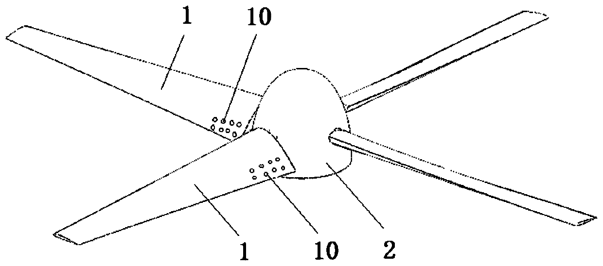
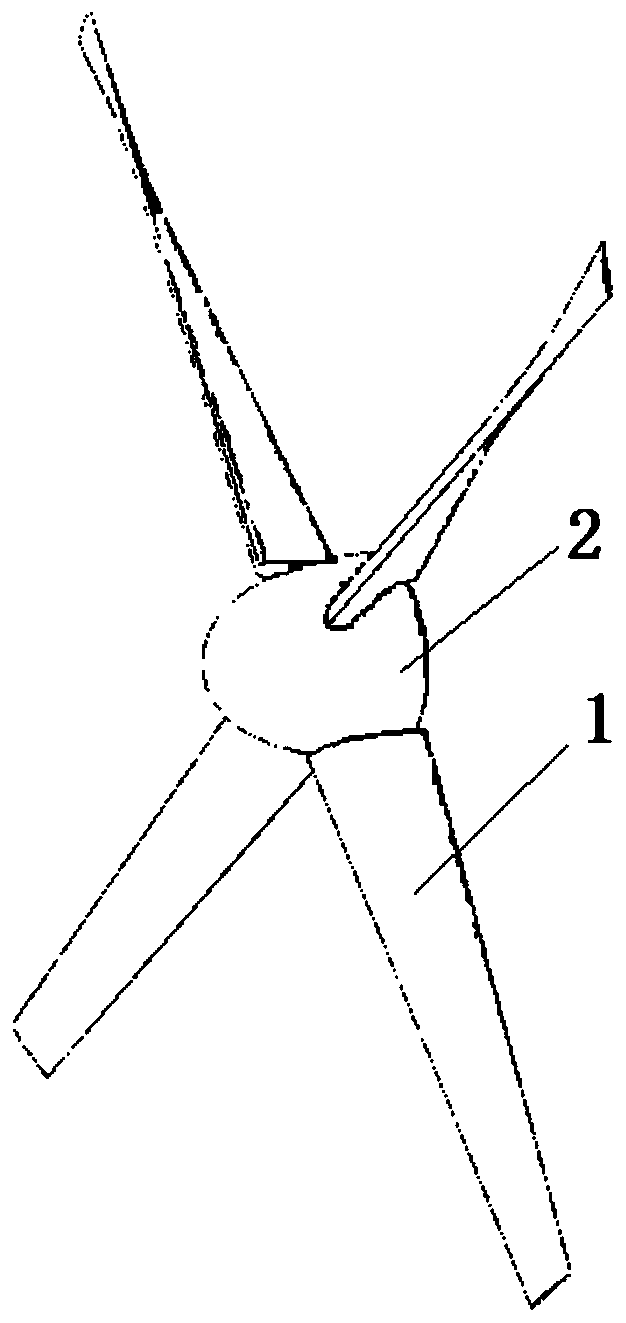
[0026] Such as Figures 1 to 3 , 5, and 6, a propeller for a tilt rotor aircraft includes a blade 1 and a hub 2, the blade 1 is fixedly connected to the hub 2 through a rotating shaft 3, and the rotating shaft 3 can be relatively When the propeller hub 2 rotates, a torsion adjustment mechanism 12 is arranged inside the propeller hub 2, and the torsion adjustment mechanism 12 can adjust and control the rotation of the rotating shaft 3, thereby driving the propeller blade 1 to rotate; further, the The twist adjustment mechanism 12 includes a rocker arm 4, a cage 5, and a drive mechanism 6. The drive mechanism 6 is specifically an actuator. One end of the rocker arm 4 is fixedly connected to the rotating shaft 3, and the other end of the rocker arm 4 has a Follower column 7, the retainer 5 has a slot 8, the follower column 7 is located in the slot 8, the retainer 5 is fixedly connected to the drive mechanism 6, and the expansion and contraction of the drive mechanism 6 The movem...
Embodiment 2
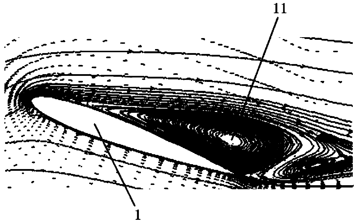
[0030] Such as figure 1 , 4 As shown in and 6, on the basis of Embodiment 1, the upper surface root of the blade 1 is provided with air blowing holes 10, and the air blowing holes 10 are evenly distributed at the root position of the upper surface of the blade 1, and the air blowing holes 10 The specific number is specifically set according to actual needs, and also includes a blowing device (not shown in the figure), and the blowing device is connected with a blowing pipe (not shown in the figure), and the blowing pipe is aligned with the blowing hole 10, The air-flow that described blowing device blows out is blown out from described blowing hole 10 through described blowing pipe; figure 1 As shown, the root of the upper surface of the blade 1 is the position where the upper surface is close to the hub 2, the blowing device is arranged on the body outside the hub 2, and the blowing pipe passes through the inner space of the hub 2 and the rotating shaft 3, and extends into ...
PUM
 Abstract
Description
Claims
Application Information
 - R&D
- Intellectual Property
- Life Sciences
- Materials
- Tech Scout
- Unparalleled Data Quality
- Higher Quality Content
- 60% Fewer Hallucinations
Browse by: Latest US Patents, China's latest patents, Technical Efficacy Thesaurus, Application Domain, Technology Topic, Popular Technical Reports.
© 2025 PatSnap. All rights reserved.Legal|Privacy policy|Modern Slavery Act Transparency Statement|Sitemap|About US| Contact US: help@patsnap.com


