Gear tilting type coaxial machine

A coaxial machine and gear technology, applied in the field of single-person aircraft, can solve the problems of high requirements for take-off and landing sites, complex structures of traditional helicopters, waste of resources, etc.

Inactive Publication Date: 2013-05-01
王略
View PDF5 Cites 0 Cited by
  • Summary
  • Abstract
  • Description
  • Claims
  • Application Information

AI Technical Summary

Problems solved by technology

[0006] The structures of these two traditional helicopters are relatively complex, and the cost and maintenance costs are extremely expensive. Due to their large fuselages, they also have high requirements for take-off and landing sites. Compared with simple daily inspections and guidance, the use of conventional helicopters is more of a resource. Wasteful, not suitable for large-scale promotion, and the complex driving skills used in both hands and feet and very high training costs are the bottlenecks restricting their development

Method used


Image

  • Gear tilting type coaxial machine
  • Gear tilting type coaxial machine
  • Gear tilting type coaxial machine

Examples


Embodiment 1

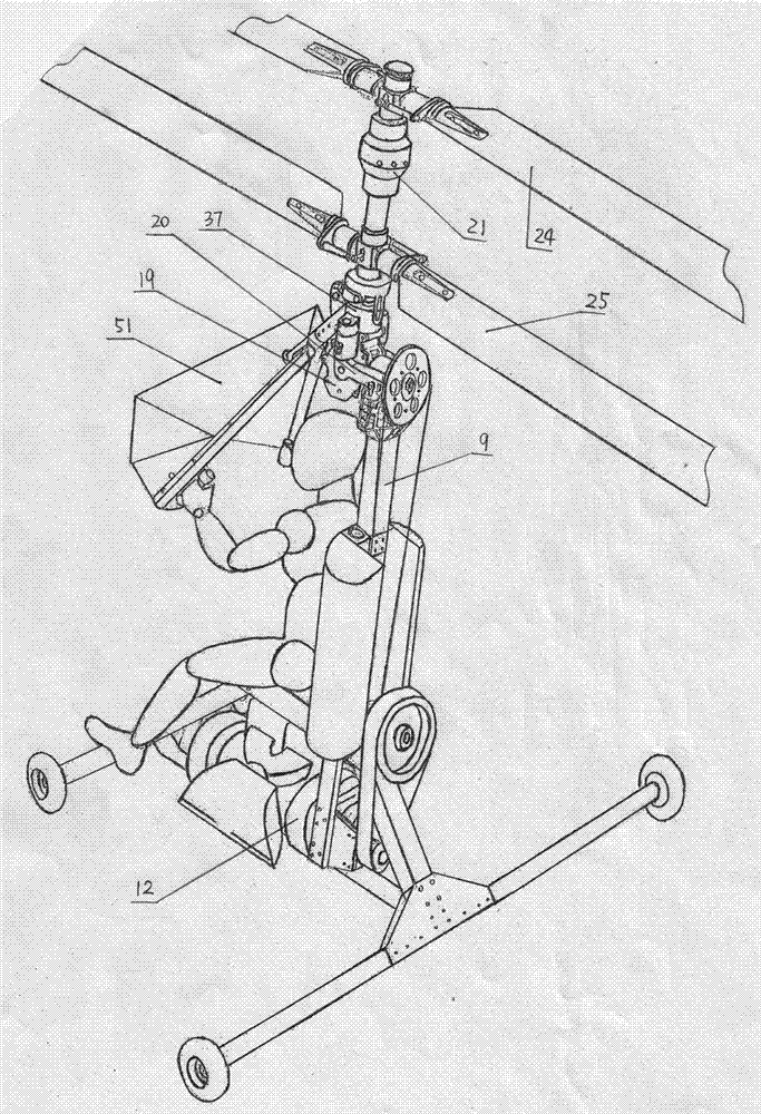
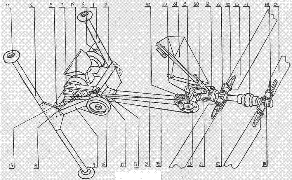
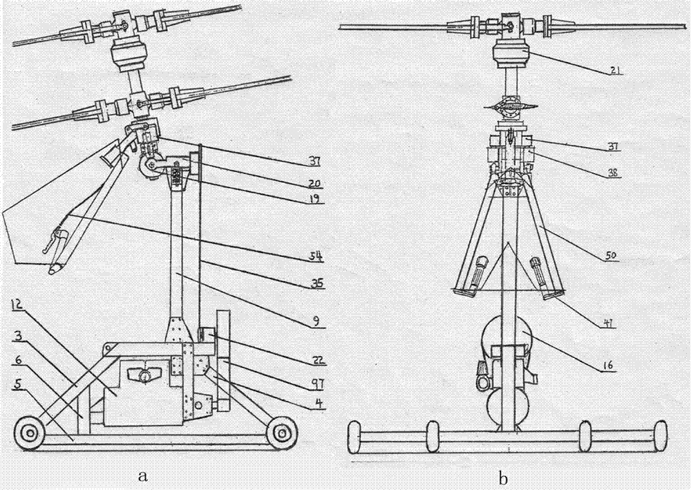
[0038] Embodiment one: see figure 1 , figure 2 , image 3 -a, image 3 -b, Figure 4 , Figure 5 , the gear tilting coaxial machine of the present invention fixes the engine 12 and the deceleration mechanism on the fuselage, and the engine 12 is connected to the tilting conversion gear mechanism fixed at the upper end of the column 9 of the fuselage through the deceleration mechanism, and the tilting conversion gear mechanism includes Tilt conversion gearbox 19 and a tilt conversion support arm 20, the power input bevel gear of the rotor tilt conversion gear mechanism is arranged on both sides of the fuselage column 9 through the bearing seat 26, and the tilt conversion support arm 20 is arranged on the power input Between the two bearing seats 26 of the small bevel gear, the tilting steering gear box 19 connects the fuselage and the tilting control rod base 37 at the lower part of the rotor shaft, and the tilting steering gear box 19 passes through the rotor shaft pitch ...

Embodiment 2

[0039] Embodiment 2: The gear tilting coaxial machine of this embodiment is different from Embodiment 1 in that it further discloses a rotor tilting steering gear mechanism.

[0040] Such as Figure 5 , Figure 6 -a, Figure 6 -b, Figure 7 As shown, the power input small bevel gear 27 axis of the rotor pitch conversion gear mechanism traverses through the power input small bevel gear bearing seats 26 on both sides of the column and the tilt conversion support arm 20 sandwiched in the middle, and the power is input to the tilt conversion The two reversing large bevel gears 28 horizontally opposed in the center of the gearbox 19, through the reversing of the large bevel gears 28, the power input on the small bevel gear 27 is transmitted to the normal state and the input power of the small bevel gear 27 The axis is on the small power output bevel gear 29 at an angle of about 90 degrees upward, and then transmitted to the rotor shaft 31 through the rotor shaft spline sleeve 30...

Embodiment 3

[0044] Embodiment 3: The gear tilting coaxial machine of this embodiment is different from Embodiment 1 or Embodiment 2 in that it adopts Figure 9 The pitch variable mechanism shown: the pitch variable control mechanism includes the built-in pitch variable mechanism of the rotor shaft and the external pitch variable mechanism. The built-in variable pitch mechanism of the rotor shaft consists of a left-hand handle 49, a small handle 52, a variable pitch cable 54, a variable pitch disc support rod 55, a variable pitch disc support rod bushing 56, a tilting control rod base 37, and a variable pitch disc support rod Screw shaft 57, variable distance disk inner sleeve 59, variable distance disk outer cover 58, variable distance pin shaft 60, variable distance disk bearing 61, variable distance disk inner sleeve snap ring 62, variable pitch disk outer jacket snap ring 63, Disc spring 64, rotor reversing gear box 21, rotor shaft spline sleeve 30, rotor shaft 31, upper rotor pitch-va...


PUM


Abstract

The invention provides a gear tilting type coaxial machine. An engine is connected with a rotor tilting reversing gear mechanism fixed at the upper end of a body upright through a speed reducing mechanism; the rotor tilting reversing gear mechanism comprises a tilting reversing gear box and a tilting reversing support arm; the tilting reversing gear box connects the body with a tilting control rod base on the lower part of a rotor shaft, and is rotatably connected with upper and lower rotors through a rotor shaft variable-pitch control mechanism and a rotor reversing counter gear box; the upper and lower rotors are of a coaxial counter-rotation dual-rotor structure; the rotor shaft variable-pitch control mechanism is matched with the rotor reversing counter gear box; a variable-pitch pullwire of the rotor shaft variable-pitch control mechanism is arranged on a V-shaped wing operation rod of a V-shaped wing operation rod control mechanism; the V-shaped wing operation rod is provided with an engine accelerator regulation handle; the V-shaped wing operation rod control mechanism is connected with the tilting control rod base; and a V-shaped wing fairing is mounted on the V-shaped wing operation rod. The coaxial machine has the advantages of low cost and simple driving mode.

Description

technical field [0001] The invention relates to a vertical take-off and landing single-person aircraft among aviation vehicles, in particular to a gear tilting coaxial machine. Background technique [0002] With the increasing burden of ground traffic and the frequent occurrence of environmental disasters, the fields of traffic guidance and fire fighting and lifesaving are facing more and more complex and difficult conditions. It is imperative to use helicopters to reduce traffic congestion and disaster prevention and rescue. [0003] Conventional single-rotor helicopters need to overcome the reaction force acting on the rotor during the working process of the main rotor to balance the reaction moment of the rotor, so the helicopter with this structure needs to be equipped with a tail rotor. When the rotor is in the rotating state, when it acts on the air, it receives the reaction torque of equal magnitude and opposite direction on the rotor at the same time, and it is trans...

Claims


Application Information

Patent Timeline
Patent Type & Authority Patents(China)
IPC IPC(8): B64C31/00B64C27/10
Inventor 王略
Owner 王略
Why Eureka
Try Eureka