
Unequal-radius tandem three-rotor helicopter

A three-rotor, tandem technology, applied in the direction of rotorcraft, fuselage, motor vehicles, etc., can solve the problems of poor handling characteristics, poor heading stability, and heavy control burden on two rotors.

Inactive Publication Date: 2019-12-24
江富余
View PDF0 Cites 0 Cited by
  • Summary
  • Abstract
  • Description
  • Claims
  • Application Information

AI Technical Summary

Problems solved by technology

[0002] At present, the known successful methods of helicopters that can realize vertical lift, hovering, front, rear, left and right flight include single rotor helicopters and tandem dual rotor helicopters. Manipulation has the advantages of simple structure and flexible manipulation, but the anti-torque of the rotor of the single-rotor helicopter needs to be balanced by the tail propeller vertical to the rotating surface. This propeller does not produce vertical lift and consumes a little power. For a pair of forward and reverse rotors with the same size at constant speeds, the counter torques of the rotors cancel each other out, which saves a little power, but both rotors must participate in the control of pitch, roll and heading, and pitch, roll and heading cannot be independent Control, the control characteristics are worse than those of single-rotor helicopters, the control burden of the two rotors is large, and the heading stability is poor

Method used


Image

  • Unequal-radius tandem three-rotor helicopter
  • Unequal-radius tandem three-rotor helicopter
  • Unequal-radius tandem three-rotor helicopter

Examples


Embodiment Construction

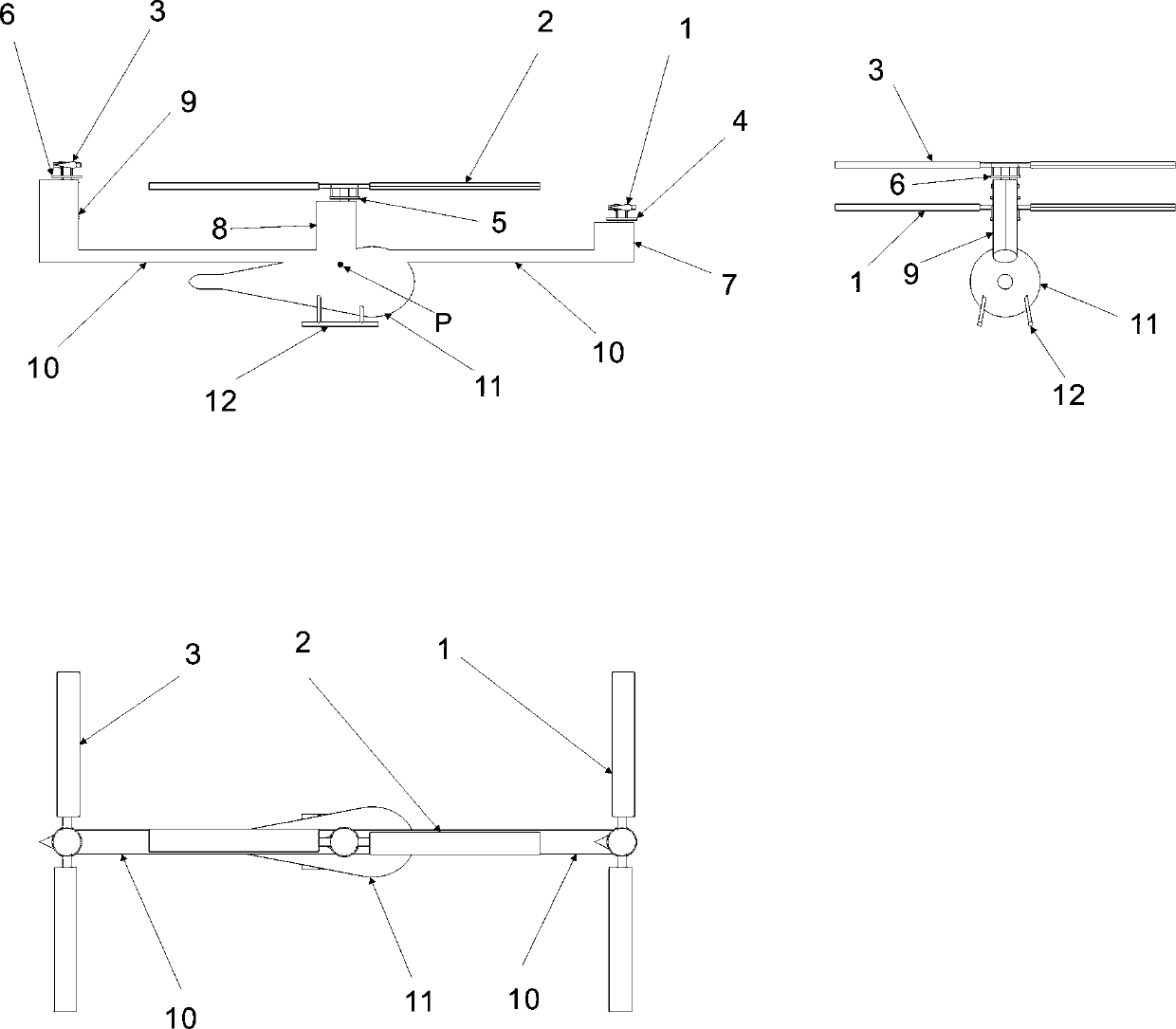
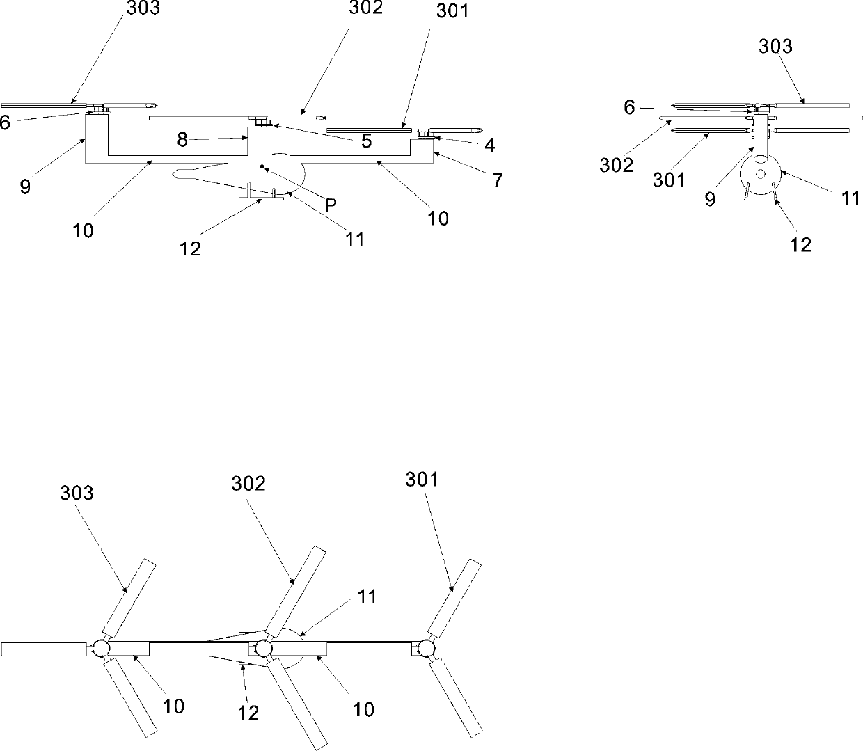
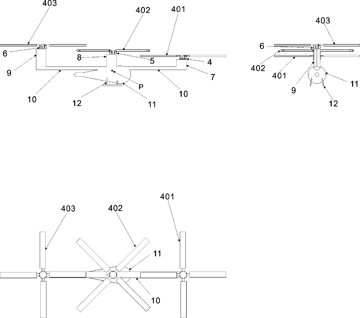
[0064] figure 1 In the shown embodiment, a longitudinal beam is arranged on the top of the fuselage (11), hereinafter referred to as the longitudinal beam (10), and the first small tower (7) is arranged on the cantilever at the front end of the longitudinal beam (10). The tower (7) plays the role of the vertical tail. The first rotor (1) consisting of two blades is set on the first small tower (7). The center of the longitudinal beam (10) is above the center of gravity (P). The top of the fuselage (11) above the center of gravity (P) is provided with a second small tower (8), and the second small tower (8) of the airfoil acts as a vertical empennage. The second rotor (2) formed by the blades, the third small tower (9) is arranged on the cantilever at the rear end of the longitudinal beam (10), and the third small tower (9) of the airfoil acts as a vertical tail. The tower (9) is provided with the third rotor (3) consisting of two blades.

[0065] Set the distance between the...


PUM


Abstract

The invention provides an unequal-radius tandem three-rotor helicopter. A longitudinal beam is arranged at the top of a helicopter body; wing-shaped small towers are correspondingly arranged at the front part, the middle part and the rear part of the longitudinal beam; the small tower at the rear part is higher than the small tower at the front part; a rotor is arranged on each small tower; rotating surfaces of the three rotors are horizontal and equally spaced; propeller blades of each rotor are connected with a rotor shaft through a propeller hub; a propeller blade swinging device consistingof a swinging hinge, an oscillation hinge and a variable pitch hinge is matched for each propeller hub; a collective pitch and periodic variable pitch controller is arranged to control the size and the direction of a rotor lift; a transmission device is arranged to enable angular velocities of the three rotors to be as same as each other so that the rotating directions of the front and rear rotors are as same as each other and are reverse to the rotating direction of the middle rotor; each rotor consists of propeller blades with same airfoil profiles, same span-chord ratios and same number; the radii of the propeller blades of the front and rear rotors are as same as each other; the radii of the propeller blades of the front and rear rotors are equal to 0.87 times of the radii of the propeller blades of the middle rotor so that the reaction torques of the three rotors offset each other; a rotor synchronizing device enables phase differences of the three rotors to be always kept constant; a landing gear is arranged at the bottom of the helicopter body; and the unequal-radius tandem three-rotor helicopter is applied to rescue, transportation and the like.

Description

technical field [0001] The invention relates to a tandem three-rotor helicopter with different radii, which adopts multi-rotor vertical lifting, hovering, front-back, left-right, and left-right flight independently of the airport. Background technique [0002] At present, the known successful methods of helicopters that can realize vertical lift, hovering, front, rear, left, and right flight include single-rotor helicopters and tandem dual-rotor helicopters. Manipulation has the advantages of simple structure and flexible manipulation, but the anti-torque of the rotor of the single-rotor helicopter needs to be balanced by the tail propeller vertical to the rotating surface. This propeller does not produce vertical lift and consumes a little power. For a pair of forward and reverse rotors with the same size at constant speeds, the counter torques of the rotors cancel each other, saving a little power, but both rotors must participate in the control of pitch, roll and heading,...

Claims


Application Information

Patent Timeline
Patent Type & Authority Applications(China)
IPC IPC(8): B64C27/08B64C27/32B64C27/473B64C27/52B64C1/06
CPCB64C1/064B64C27/08B64C27/32B64C27/473B64C27/52
Inventor 江富余
Owner 江富余
Learn More