Electric spiral lifting rod

An electric screw and lifting rod technology, applied in the field of lifting rods, can solve the problems of difficult processing, complex structure, limitation of lifting height and lifting weight, etc., and achieve a concise connection structure, high strength, and excellent reliability and stability. Effect

Active Publication Date: 2011-04-06
崔鲁彬
View PDF8 Cites 30 Cited by
  • Summary
  • Abstract
  • Description
  • Claims
  • Application Information

AI Technical Summary

Problems solved by technology

[0002] At present, the structural design of the lifting joints used to erect various facilities and lift weights is complex, and cannot meet the requirements of various environments for its products, and there are some shortcomings
[0003] 1. There are limitations on the lifting height and lifting weight
[000

Method used


Image

  • Electric spiral lifting rod
  • Electric spiral lifting rod
  • Electric spiral lifting rod

Examples


Embodiment Construction

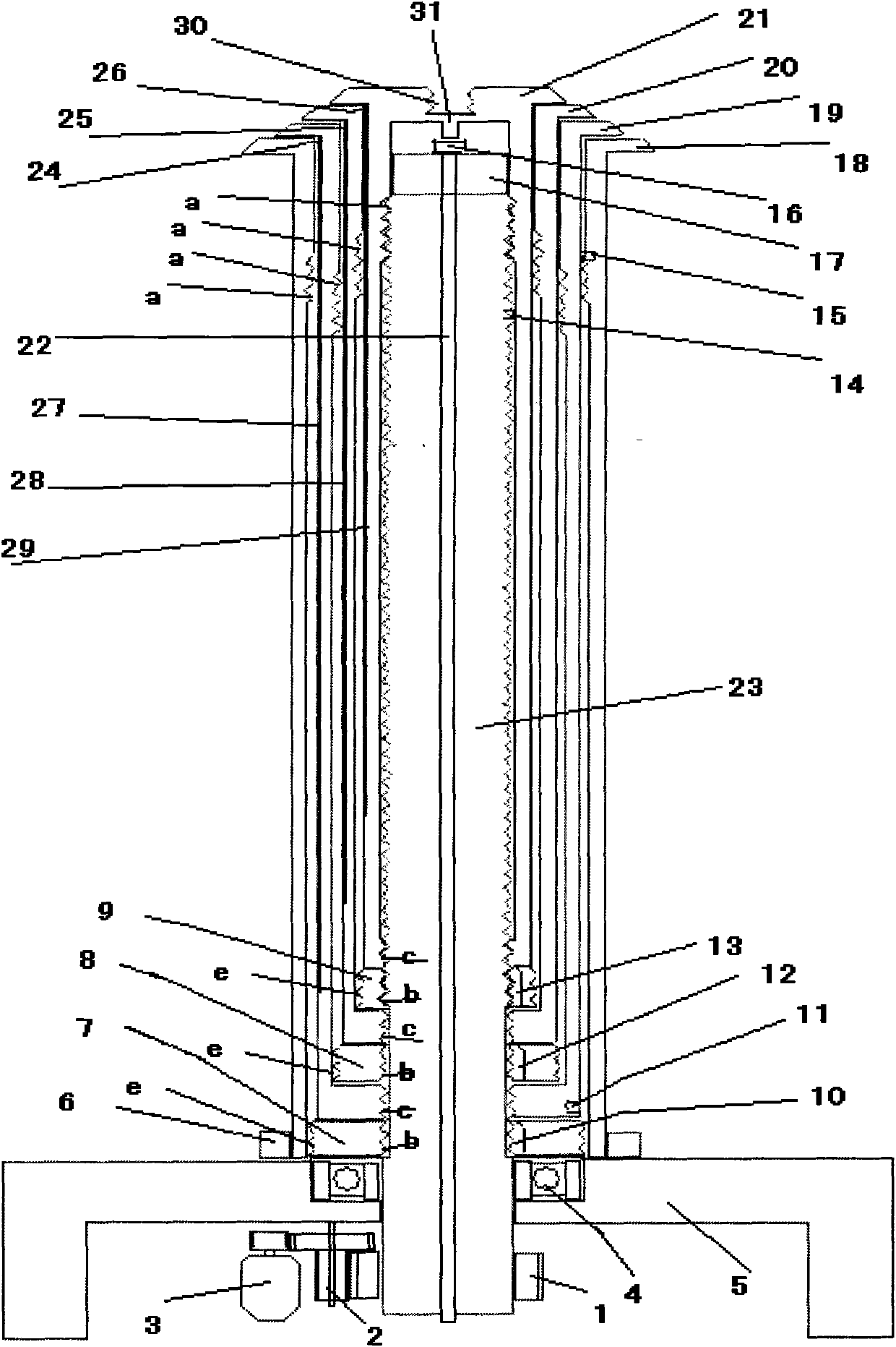
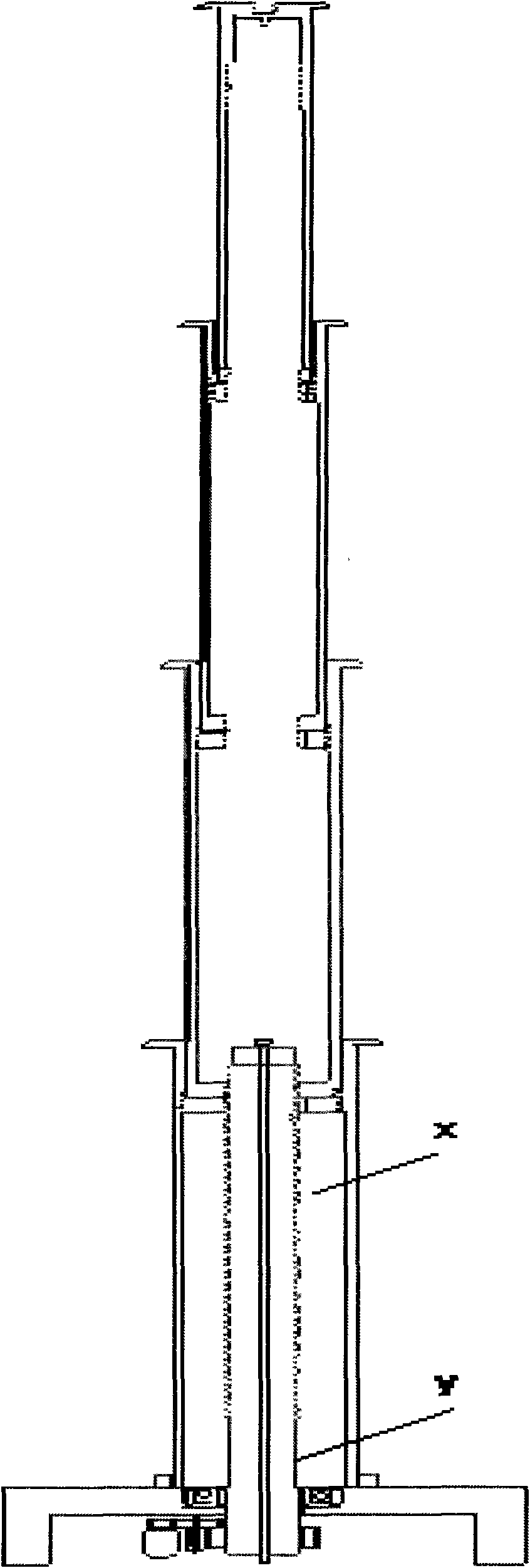
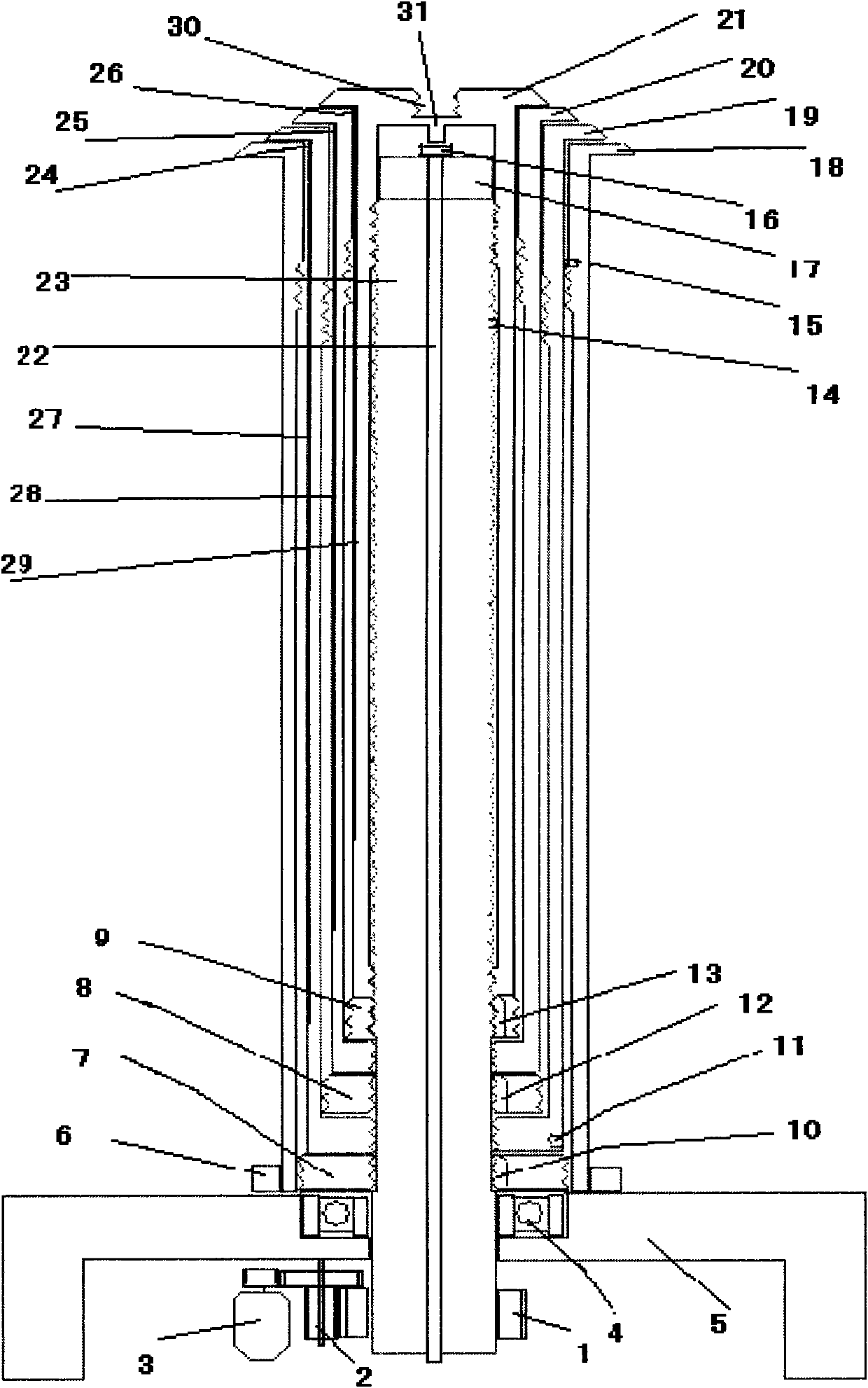
[0017] Figure 1 to Figure 2 Among them, there is a base 5 under the electric spiral lifting rod, and a bearing 4 is installed on the plane at the center of the base. Above the base, there are n circular lifting joint rods 18.19 whose axes are on the same line and whose diameters are sequentially nested together from large to small. .20.21 (this manual takes 4 lifting joints as an example, if there are n lifting joints, the working principle is exactly the same n=3-n.n>3), the inner upper part of each lifting joint has reverse thread a and lower thread c , the bottom of the lower thread is connected with a fastening nut 7.8.9, the outer thread e of the fastening nut is a reverse thread, and the inner thread b has a small card slot 10.12.13 perpendicular to it. There is a stop switch 15 above the inside of the penultimate lifting joint, and correspondingly there is a stop peak 11 below the outside of the penultimate lifting joint, and there is a stop and landing peak 31 above t...


PUM


Abstract

The invention relates to an electric spiral lifting rod, which is characterized in that a screw rod is driven by a motor to rotate and is sequentially and directly engaged with screw threads at the lower part of the inner side of each lifting section rod so that each lifting section rod can move up and down section by section. In the electric spiral lifting rod, n circular lifting section rods are arranged on a base of the electric spiral lifting rod and are sleeved together in sequence from the large diameter to the small diameter, wherein n=3-n, and n is greater than 3; and the upper parts and the lower parts of the inner sides of the n circular lifting section rods are respectively provided with a section of screw threads, the upper parts are provided with left-hand screw threads, the lower screw threads ordinarily lean against the threadless part of the screw rod, and the lower parts of the lower screw threads are respectively provided with a fastening screw cap which can move up and down along each lifting section rod and can rotate along the axes of the fastening screw cap. When all lifting section rods are sequentially lifted in places section by section, every adjacent lifting section rods are mutually engaged and connected through the left-hand screw threads at the outer side of the fastening screw cap of each lifting section rod and the left-hand screw threads at the upper parts of the inner side of the adjacent lifting section rods, the connection strength among the electric spiral lifting rods is high, and the reliability is good. The electric spiral lifting rod is used for producing superhigh erection type facilities and lifting weight products and can benefit the great reduction of the production cost because of the concise structure of the electric spiral lifting rod per se.

Description

technical field [0001] The invention relates to an electric spiral lifting rod, in particular, it is a lifting rod in which a motor drives a screw rod to rotate and sequentially directly drives n circular lifting joint rods to move up and down. Background technique [0002] At present, the structural design of the lifting joints used for erecting various facilities and lifting weights is complex, and cannot meet the requirements of various environments for its products, and there are some shortcomings. [0003] 1. There are limitations on the lifting height and lifting weight. [0004] 2. When the lift is in place, it will gradually slide down, resulting in a poor long-term maintenance state. [0005] 3. The complex structure brings bulky appearance and increased failure rate. [0006] 4. Due to the complex structure, processing is difficult and the manufacturing cost is increased. Contents of the invention [0007] The object of the present invention is to improve the ...

Claims


Application Information

Patent Timeline
IPC IPC(8): B66F3/08B66F3/44
Inventor 崔鲁彬
Owner 崔鲁彬
Why Eureka
Try Eureka