Compound mud-rock flow discharge and guide trough

A technology for drainage channel and debris flow, which is applied in water conservancy projects, artificial waterways, embankments, etc., can solve the problems of single type of debris flow drainage channel and low land utilization rate, so as to improve land utilization rate, alleviate human-land conflict, The effect of improving the utilization rate

Inactive Publication Date: 2011-12-14
INST OF MOUNTAIN HAZARDS & ENVIRONMENT CHINESE ACADEMY OF SCI
View PDF2 Cites 1 Cited by
  • Summary
  • Abstract
  • Description
  • Claims
  • Application Information

AI Technical Summary

Problems solved by technology

[0005] The purpose of the present invention is to address the deficiencies of the prior art, that is, to provide a compound debris flow drainage channel that maximizes the land utilization rate for the current debris flow drainage channel with a single type and low land utilization rate; In the section, combine the urban road with the main channel of the drainage channel, or combine the hydrophilic park with the main channel of the drainage channel; when passing through the farmland section, combine the field road with the main channel of the drainage channel, or combine the temporary cultivated land with the main channel Combination of guide trough and main trough; the use of multiple debris flow drainage troughs instead of a single type not only improves the drainage capacity of the trough and the ability to protect the protected objects, but also improves the land utilization rate

Method used


Image

  • Compound mud-rock flow discharge and guide trough
  • Compound mud-rock flow discharge and guide trough
  • Compound mud-rock flow discharge and guide trough

Examples


Embodiment 1

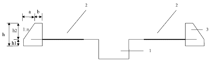
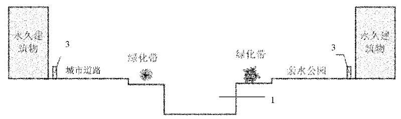
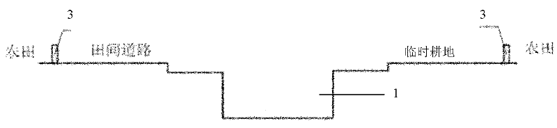
[0026] Such as figure 1 , figure 2 , image 3 Shown. The drainage area of ​​a debris flow is 24.1km 2 The slope of the accumulation fan is 9.0%. On the 2500m long debris flow accumulation fan, build the compound debris flow drainage channel. The compound debris flow drainage channel includes a drainage channel main channel 1 for draining debris fluid under the design standard, and a drainage channel buffer zone 2 for draining debris fluid that exceeds the design standard; the drainage channel buffer zone 2 is located A gravity retaining wall 3 is provided on both sides of the main groove 1 of the row guide groove, and the boundary of the buffer area 2 of the row guide groove. Because the protection object is particularly important, the design standard of the main channel 1 of the drainage channel is designed according to the once-in-50-year event. The maximum scale of the entire compound debris flow drainage channel is once in 200 years (that is, the maximum discharge scale ...

Embodiment 2

[0030] Such as figure 1 , image 3 Shown. The drainage area of ​​a debris flow is 14.1km 2 , The slope of the accumulation fan is 7.5%. In order to protect the railways and highways at the mouth of the ditch, the compound debris flow drainage channel was built on the 2000m long debris flow accumulation fan. The compound debris flow drainage channel includes a drainage channel main channel 1 for draining debris fluid under the design standard, and a drainage channel buffer zone 2 for draining debris fluid that exceeds the design standard; the drainage channel buffer zone 2 is located A gravity retaining wall 3 is provided on both sides of the main groove 1 of the row guide groove, and the boundary of the buffer area 2 of the row guide groove. The design standard of the main channel 1 of the drainage channel is designed according to the once-in-20-year event. The maximum debris flow standard for the entire compound debris flow drainage channel is once in 100 years (that is, the...


PUM


Abstract

The invention discloses a compound mud-rock flow discharge and guide trough comprising a main discharge and guide trough for the mud-rock flow body under a discharge design standard and discharge and guide trough buffer regions for the mud-rock flow body under the discharge ultra-design standard. The discharge and guide trough buffer regions are located on both sides of the main discharge and guide trough and the boundary of the drainage trough buffer regions are provided with gravity retaining walls. Compared with the prior art, the invention fully utilizes the dangerous regions (a mud-rock flow flooding region under the design standard of main ultra discharge and guide trough) on both sides of the main discharge and guide trough together with the main discharge and guide trough to form the compound mud-rock flow discharge and guide trough, can not only improve the discharge and guide ability of the mud-rock flow discharge and guide trough and enhance the protection capability of thedischarge and guide trough on objects on both sides, but also effectively improve the land use ratio and benefit the relieving of the human-land contradiction as for towns and market towns in mountainous areas extremely lack of land resources, and ensure sustainable development in mountainous areas.

Description

Technical field [0001] The invention relates to a debris flow prevention technology, in particular to a compound debris flow drainage channel with maximum land utilization rate. Background technique [0002] Debris flow disasters are one of the main types of geological disasters in my country. With the economic development of mountainous areas and the deepening of the western development, the demand for debris flow engineering treatment is becoming more and more vigorous. The debris flow drainage channel is one of the most commonly used debris flow treatment engineering measures. It has been widely used in the past and will also be used in the future debris flow engineering treatment. Will be widely used. [0003] The debris flow drainage channel is designed in accordance with certain standards. When the scale of the debris flow is within the drainage design standard, the drainage channel can drain the debris flow smoothly; when the scale of the debris flow exceeds or greatly exce...

Claims


Application Information

Patent Timeline
Patent Type & Authority Patents(China)
IPC IPC(8): E02B5/00E02B3/10E01F7/04E02D29/02
CPCE02B3/10
Inventor 陈晓清崔鹏游勇李德基黄凯
Owner INST OF MOUNTAIN HAZARDS & ENVIRONMENT CHINESE ACADEMY OF SCI
Why Eureka
Try Eureka