Design method for high-efficiency overload-free vortex pump impeller

A design method and no-overload technology, applied to parts, pumps, and pump components of pumping devices for elastic fluids, can solve problems such as energy waste, increased power reserve factor, and increased investment, so as to reduce investment, Capacity reduction and energy saving effects

Inactive Publication Date: 2011-04-06
江苏振华海科装备科技股份有限公司
View PDF0 Cites 17 Cited by
  • Summary
  • Abstract
  • Description
  • Claims
  • Application Information

AI Technical Summary

Problems solved by technology

[0003] In the past, the main way to solve this problem was to increase the power reserve factor, and multiply the shaft power at the design point of the swirl pump by a factor not less than 1.4

Method used


Image

  • Design method for high-efficiency overload-free vortex pump impeller
  • Design method for high-efficiency overload-free vortex pump impeller
  • Design method for high-efficiency overload-free vortex pump impeller

Examples


Embodiment Construction

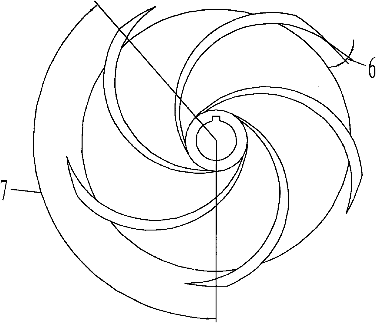
[0028] figure 1 with figure 2 Together determine the impeller shape for this embodiment. Like most centrifugal pump impellers, it has an impeller back cover (1) and is an open impeller. The present invention determines the outlet width b of the impeller blades through the following relational expressions 2 , The diameter of the outer circle of the impeller blade D 2 , The outlet placement angle β of the impeller blade 2 , impeller blade wrap angle and the vane outlet inclination angle α, so that the performance of the swirl pump in this embodiment meets the requirement of no overload.

[0029] D 2 = 16 2 gH n ( sin β 2 ) 0.25 ;

[0030] b ...


PUM


Abstract

The invention relates to a design method for a high-efficiency overload-free vortex pump impeller. By designing blades of the impeller to be cambered blades with double curvature or single curvature and designing installation performance parameters of the outlet diameter of the blades, the outlet diameter of the blades changes according to a certain rule. The vortex loss of the impeller at the outlet can be reduced, and overload is not produced for the operation in a full-head range while the vortex pump runs at a high-efficiency region.

Description

technical field [0001] The invention relates to a design method for main parts of a non-variable pump, in particular to a design method for an impeller of a high-efficiency non-overload swirl pump. Background technique [0002] At present, the existing swirl pumps use radioactive impellers, which can only ensure the operation of the swirl pump within a narrow flow range. If the operating conditions exceed the operable range of the pump, the motor may burn out. However, the operating conditions of the swirl pump vary greatly, and the head of the pump device will change greatly, resulting in the actual working point of the swirl pump moving within a large flow range. According to statistics, about 70% of the faults of the repaired submersible pumps are caused by overload. The reliability of this type of pump is low due to the failure of the motor due to overload, which greatly limits the scope of use of the swirl pump. This requires that the impeller we design can operate in...

Claims


Application Information

Patent Timeline
IPC IPC(8): F04D29/22
Inventor 庄卫将邱勇纪炜李林军
Owner 江苏振华海科装备科技股份有限公司
Why Eureka
Try Eureka