Method for manufacturing rotor and cutting apparatus

A manufacturing method and rotor technology, applied in the field of cutting device for cutting magnet base material, manufacturing of rotor, and cutting device, can solve the problems of lower yield, more chips, higher manufacturing cost, etc., and achieve high contact resistance and lower cost , the effect of reducing eddy loss

Inactive Publication Date: 2014-01-22
TOYOTA JIDOSHA KK
View PDF8 Cites 1 Cited by
  • Summary
  • Abstract
  • Description
  • Claims
  • Application Information

AI Technical Summary

Problems solved by technology

[0004] However, in the method for producing a cut magnet in the following Patent Document 1, when the magnet base material 130A is cut, a lot of chips are generated, and the expensive magnet base material 130A is wasted.
In addition, an expensive and consumable diamond tip is attached to the cutting tool
Therefore, there is a problem that the production cost of the cutting magnet 130 is high due to the decrease in the yield of the cutting magnet 130 and the periodic replacement of the cutting blade, that is, the production cost of the rotor incorporating the cutting magnet 130 is high.
In addition, the process of forming the insulating coating 140 also increases the manufacturing cost of the rotor (cutting the magnet 130 ).

Method used


Image

  • Method for manufacturing rotor and cutting apparatus
  • Method for manufacturing rotor and cutting apparatus
  • Method for manufacturing rotor and cutting apparatus

Examples


no. 1 Embodiment approach

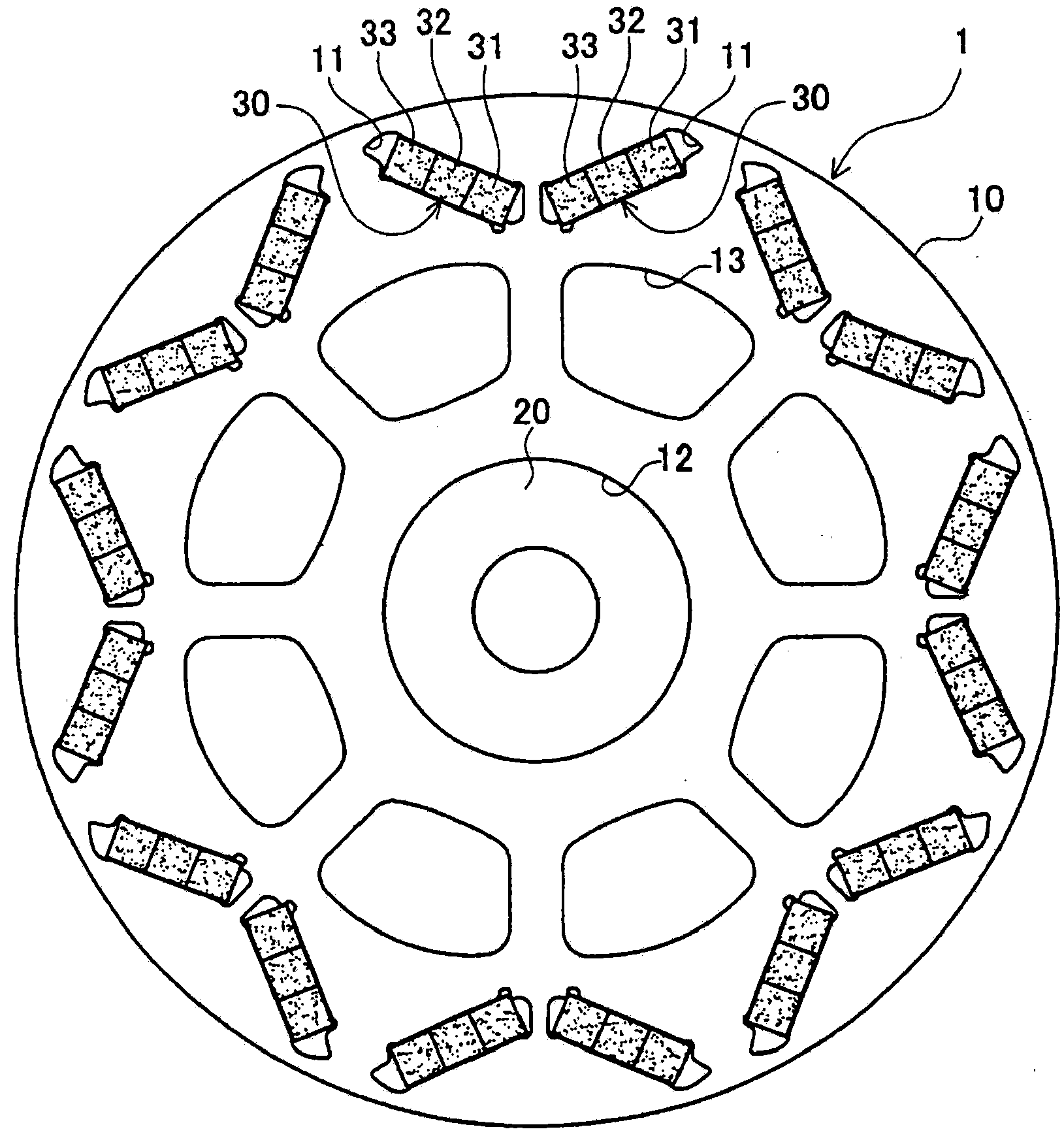
[0062] Hereinafter, a method for manufacturing a rotor and a cutting device according to the present invention will be described with reference to the drawings. figure 1 is a plan view showing the rotor 1 . Such as figure 1 As shown, the rotor 1 includes a rotor shaft 20, a cut-off magnet 30, and a rotor core 10 as a main body of the rotor.

[0063] The rotor core 10 is formed by laminating a plurality of annular electromagnetic steel sheets. Such as figure 1 As shown, the rotor core 10 has a plurality of slots 11 on the outside in the radial direction, a central hole 12 in the center of the shaft, and a plurality of lightening holes 13 in the middle in the radial direction.

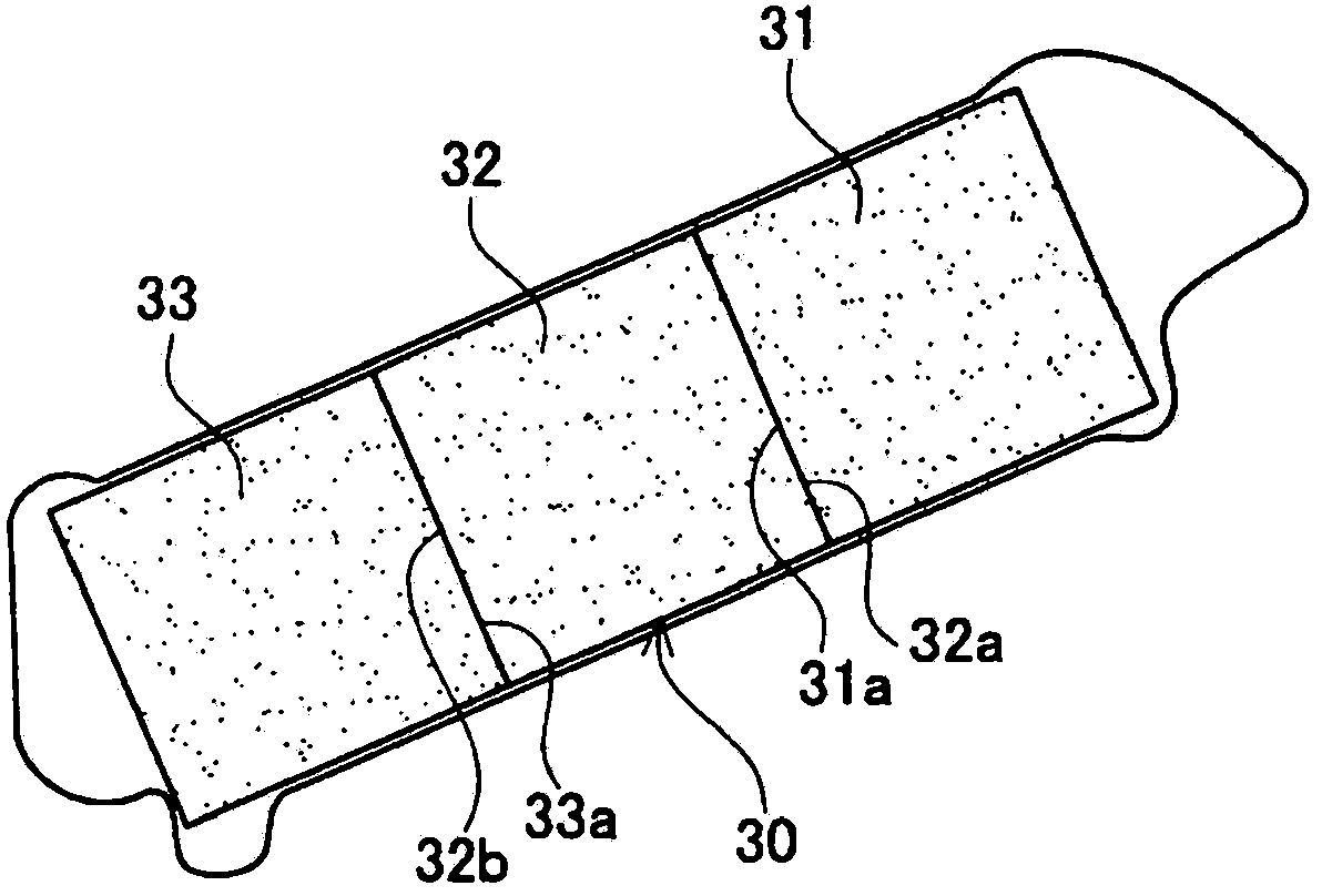
[0064] Each slot 11 is used for assembling the split magnet 30 , and each slot 11 penetrates the rotor core 10 in the axial direction. A pair of adjacent slots 11 are arranged at equal intervals along the circumferential direction of the rotor core 10 and are substantially V-shaped in plan view. ...

no. 2 Embodiment approach

[0106] Next, use Figure 11 to Figure 14 The second embodiment will be described. Figure 11 It is a schematic overall configuration diagram of a cutting device 40A in the second embodiment. exist Figure 11 In , the state where the magnet base material 30A is divided into the first magnet piece 31 and the second magnet piece 32 is shown. Such as Figure 11 As shown, the cutting device 40A has a surface processing mechanism 90 . here, Figure 12 yes Figure 11 The Z-Z section view.

[0107] Such as Figure 12 As shown, the surface processing mechanism 90 includes a spacer 91 , a connecting pin 92 , a holding member 93 , an actuator 94 , a vibrating device 95 , a connecting pin 96 and a nut 97 . The partition 91 restricts or allows the central wall 61 to move relative to the side walls 52 , 53 in the axial direction of the rotation shaft 64 (hereinafter simply referred to as “axial direction”). exist Figure 12 , the spacer 91 fills the gap D1 between the side wall 52...

no. 3 Embodiment approach

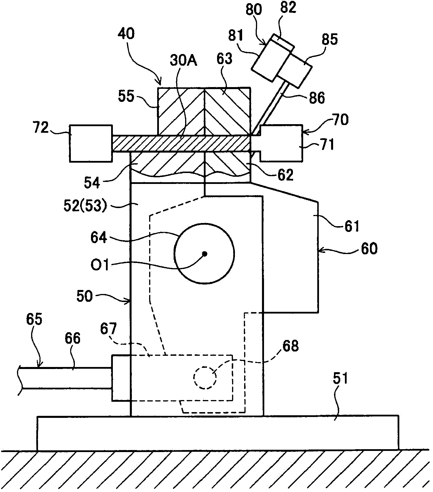
[0117] Next, use Figure 15 ~ Figure 17 The third embodiment will be described. Figure 15 It is a schematic overall configuration diagram of the cutting device 40B in the third embodiment. exist Figure 15 In , the state before cutting the magnet base material 30A is shown. This cutting device 40B does not have the surface processing mechanisms 80 and 90 of the first and second embodiments.

[0118] and, if Figure 15 As shown, in this cutting device 40B, between the fixed lower jig 54 and the movable lower jig 62 and between the fixed upper jig 55 and the movable upper jig 63 , the magnet base material 30A is cut. ( Figure 15 left and right direction) is formed with a gap D3. Other configurations of the third embodiment are the same as those of the first and second embodiments, and therefore descriptions of these configurations are omitted.

[0119] Next, the process of surface-processing the fractured surface 31a of the 1st magnet piece 31 in 3rd Embodiment is demon...


PUM

PropertyMeasurementUnit
sizeaaaaaaaaaa
sizeaaaaaaaaaa
sizeaaaaaaaaaa

Abstract

In a method for manufacturing a rotor, a plurality of cut magnet pieces (31, 32) are assembled in a rotor core (10) with both cut surfaces (31a, 32a) of the cut magnet pieces (31),(32) in a engaged state. The production method for the rotor includes a cutting step and a surface treating step. In the cutting step, a magnetic substrate (30A) having a recess (30a) formed in a surface thereof is cut using the recess (30a) as a starting point, thereby forming a first magnet piece (31) and a second magnet piece (32). In the surface treating step, cut surfaces (31a) are surface treated, so as to reduce protrusions (TO) on the cut surfaces (31a) of the first magnet piece (31). Accordingly, the engagement between the cut surfaces (31a, 32a) is poor, the contact area is reduced, and the contact resistance is increased. As a result thereof, the eddy currents in the cut magnets (30) flow less easily, and a loss resulting from the eddy currents may be decreased.

Description

technical field [0001] The present invention relates to a method of manufacturing a rotor in which a plurality of cut (Japanese: cut) magnet pieces are assembled to a rotor main body, and in particular, relates to a method of manufacturing a rotor that can reduce losses caused by eddy currents by making cut magnets . Also, the present invention relates to a cutting device for cutting a magnet base material, and particularly relates to a cutting device capable of reducing loss due to eddy currents. Background technique [0002] In electric machines, when large magnets are assembled directly to the rotor body, the magnetic flux causes eddy currents in the magnets. In particular, in a motor for a hybrid vehicle, the fluctuation of the magnetic flux is large, and a large eddy current is generated. This eddy current heats up the magnet and degrades the performance of the motor. Therefore, the eddy current causes an increase in fuel consumption. In order to reduce losses cause...

Claims


Application Information

Patent Timeline
Patent Type & Authority Applications(China)
IPC IPC(8): H02K1/27
CPCH01F7/02H02K1/02H02K1/276H01F41/0253Y10T29/49012Y10T29/51H02K15/03H02K1/27
Inventor 西隈靖深谷哲义建部胜彦雪吹晋吾
Owner TOYOTA JIDOSHA KK
Why Eureka
Try Eureka