Lifting rod component

A lifting rod and component technology, which is applied in the field of lifting rod components on showers in the bathing field, can solve problems such as inconvenient assembly, and achieve the effects of convenient assembly, large contact area, and firm locking

Inactive Publication Date: 2012-08-22
XIAMEN SOLEX HIGH TECH IND CO LTD
View PDF7 Cites 0 Cited by
  • Summary
  • Abstract
  • Description
  • Claims
  • Application Information

AI Technical Summary

Problems solved by technology

[0003] The present invention provides a lifting rod assembly, which overcomes the inconvenient assembly problem of the lifting rod assembly in the background art

Method used


Image

  • Lifting rod component
  • Lifting rod component
  • Lifting rod component

Examples


Embodiment Construction

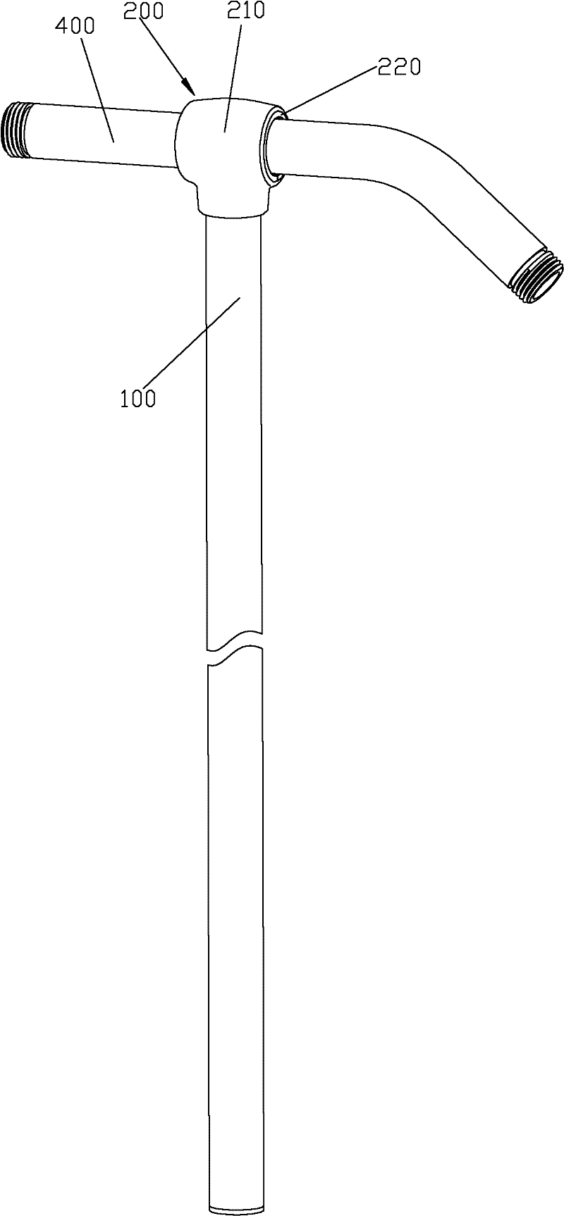
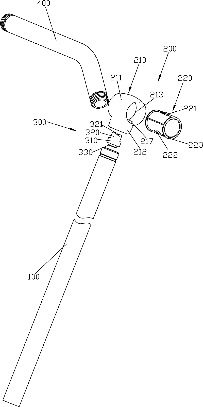
[0038] Please check Figure 1 to Figure 3 , the lifting rod assembly, which includes a lifting rod 100, a body unit 200, a friction plate 300, a suction cup mechanism and a sliding seat. The lifting rod assembly is connected to the American-style support arm 400 , and the sliding seat is connected to the lifting rod 100 so as to be able to slide up and down, and is used for plugging the hand shower.

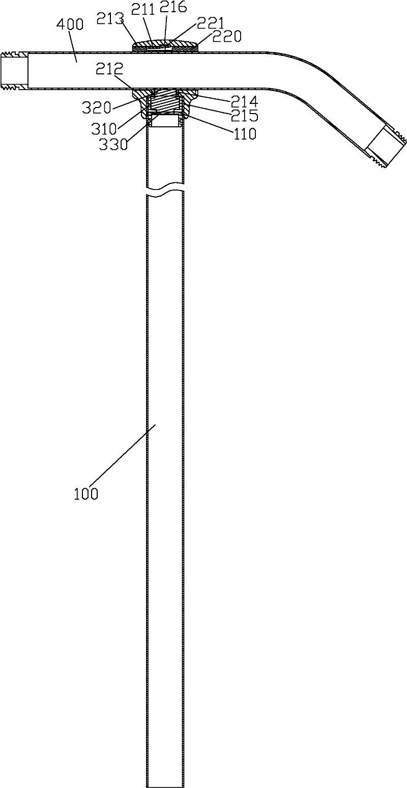
[0039] The outer turning surface of the upper end of the lifting rod 100 is provided with external threads, and the inner turning surface of the upper end is provided with a step 110 , and there is a distance between the step 110 and the upper end surface of the lifting rod 100 .

[0040] Please check Figure 1 to Figure 8 , the body unit 200 includes a body 210 and a sleeve 220 .

[0041] The body 210 includes a positioning sleeve 211 and a fixing head 212 fixed under the positioning sleeve 211 . The inner hole of the positioning sleeve 211 is a through hole 213, and a card g...


PUM


Abstract

The invention discloses a lifting rod component, which is connected with a support arm. The lifting rod component comprises a body unit, a lifting rod and a friction plate, wherein the body unit is provided with a through sleeve joint hole and a connecting hole passing through the inside and the outside of the sleeve joint hole; the sleeve joint hole is sleeved outside the support arm; the upper end part of the lifting rod is threaded in the connecting hole of the body unit; the friction plate is arranged on the upper end part of the elevating rod and matched with the support arm; and the compression degree between the friction plate and the support arm can be controlled according to the threaded screwing degree between the lifting rod and the connecting hole of the body unit. The liftingrod component has the advantages that: the compression degree between the friction plate and the support arm can be controlled according to the threaded screwing degree between the lifting rod and the connecting hole of the body unit; locking connection between the lifting rod component and the support arm is controlled; and the lifting rod component has a simple structure and high practicability, is convenient to assemble, and can be directly applied to the conventional American support arm.

Description

technical field [0001] The invention relates to a lifting rod assembly, in particular to a lifting rod assembly used on a shower in the bathing field. Background technique [0002] A traditional lifting rod assembly includes an upper and lower wall seat and a lifting rod, the upper and lower wall seats are fixed on the wall, and the lifting rod is fixed between the upper and lower wall seats. Because two wall seats are used in the traditional lifting rod assembly, the construction difficulty and construction cost are increased, and the material and manufacturing costs are increased. For the above-mentioned shortcomings, someone has proposed a solution, such as ZL200820103272.4 and ZL200720118108.6 disclosed in the Chinese patent database. They all provide a technical solution using only one wall seat. There are following deficiencies: 1. The structure is complicated, and the assembly is very inconvenient; 2. It cannot be directly used on the existing American-style support ...

Claims


Application Information

Patent Timeline
Patent Type & Authority Patents(China)
IPC IPC(8): F16B7/08E03C1/06B05B15/06
Inventor 彭华胜尧华李仁忠周华松
Owner XIAMEN SOLEX HIGH TECH IND CO LTD
Why Eureka
Try Eureka