Extra-high voltage direct current line boundary element method adopting polar wave wavelet energy ratio

A technology of ultra-high voltage direct current and wavelet energy, which is applied to electrical components, emergency protection circuit devices, etc.

Active Publication Date: 2011-04-06
KUNMING UNIV OF SCI & TECH
View PDF4 Cites 30 Cited by
  • Summary
  • Abstract
  • Description
  • Claims
  • Application Information

AI Technical Summary

Problems solved by technology

Nevertheless, the currently used DC line traveling wave protection will still be affected

Method used


Image

  • Extra-high voltage direct current line boundary element method adopting polar wave wavelet energy ratio
  • Extra-high voltage direct current line boundary element method adopting polar wave wavelet energy ratio
  • Extra-high voltage direct current line boundary element method adopting polar wave wavelet energy ratio

Examples


Embodiment Construction

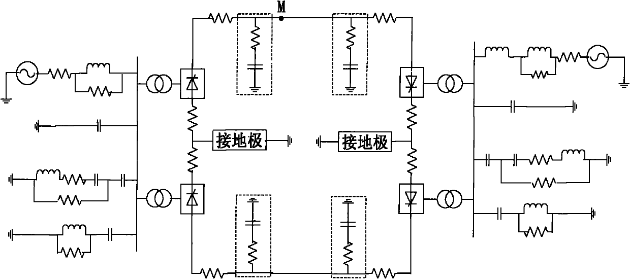
[0080] Simulation model such as figure 1 As shown, a positive ground fault occurs at a distance of 1km from the protection installation, the fault transition resistance is 0.1Ω, the time window length is 2ms, and the sampling frequency is 100kHz.

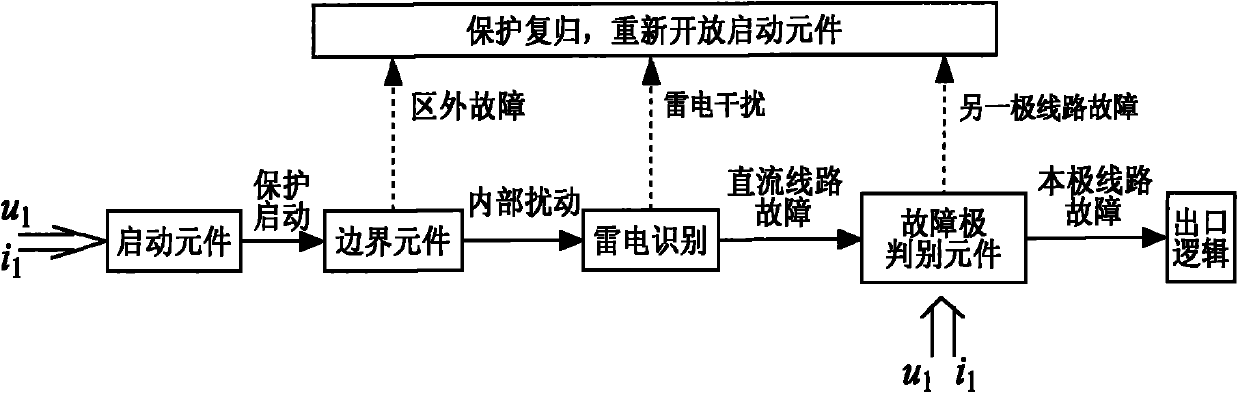
[0081] (1) After the DC line fails, the starting element starts immediately, according to the formula:

[0082] p 1 (k)=Z P × i 1 (k)-u 1 (k) (11)

[0083] p 2 (k)=Z P × i 2 (k)-u 2 (k) (12)

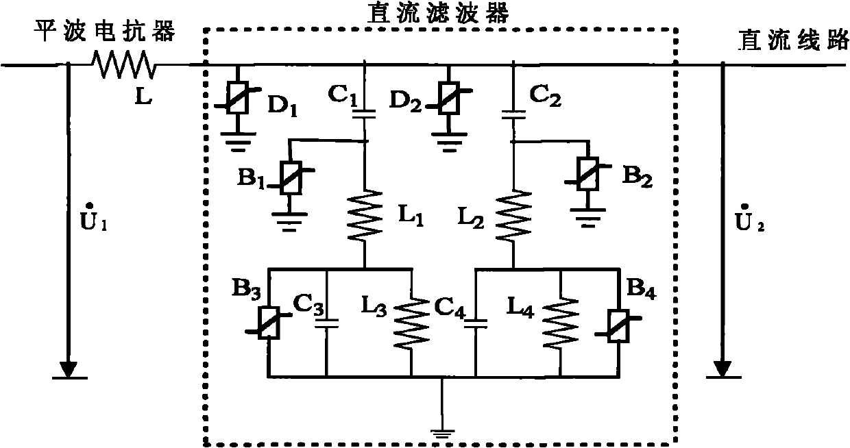
[0084] Find the positive polar wave and the negative polar wave, the polar wave waveform is as follows Figure 5 Shown; where, Z p is the polar wave impedance of the DC transmission line, u 1 (k) is the positive DC voltage, i 1 (k) is positive direct current, u 2 (k) is the negative DC voltage, i 2 (k) is the negative direct current, k=1, 2, 3...N, N is the sampling sequence length;

[0085] (2) According to the formula

[0086]

[0087]

[0088] Carry out wavelet transformation on the positive pole wave to obtain high-f...


PUM


Abstract

The invention provides an extra-high voltage direct current line boundary element method adopting polar wave wavelet energy ratio, belonging to the technical field of relay protection of electric power systems. The method comprises the following steps: when the direct current line has fault, computing the anode line polar wave voltage and the cathode line polar wave voltage according to the direct current voltage and direct current of the two poles measured in the relay location; selecting the discrete polar wave voltage signal with sampling sequence length of 200 after fault to undergo wavelet transform to obtain a series of high/low frequency polar wave voltage wavelet transform parameters and computing the modules of the high/low frequency polar wave voltage wavelet transform parameters; computing the ratio of high/low frequency energy of polar wave voltage after extracting the high/low frequency components of polar wave voltage according to the obtained modules; and distinguishingthe area fault from the out-area fault according to the ratio of high/low frequency energy. Lots of simulation results show the method has good effect.

Description

technical field [0001] The invention relates to the technical field of relay protection for power systems, in particular to a boundary element method for UHV direct current transmission lines using polar wave voltage wavelet transform energy ratios. Background technique [0002] After a DC line fault occurs, the DC pole control system can be used to quickly limit and eliminate the fault current, but at the same time, due to the function of the current regulator, the fault current is much smaller than that of the AC line, and the correct fault current cannot be determined solely by the magnitude of the fault current voltage. Therefore, it can be considered to detect DC line faults through transient components and take correct protection measures. Traveling wave protection is designed considering that the amplitude and direction of transient current and voltage traveling waves generated at the moment of line fault are not controlled by the control system, and can accurately re...

Claims


Application Information

Patent Timeline
IPC IPC(8): H02H7/26
Inventor 束洪春贺婷田鑫萃刘可真张广斌孙士云方毅安娜
Owner KUNMING UNIV OF SCI & TECH
Why Eureka
Try Eureka