Fuel tank insert part weld molding method and fuel tank

A technology for fuel tanks and components, which is applied in the field of cladding and forming of embedded components, to achieve the effect of reliable cladding

Inactive Publication Date: 2015-01-14
HONDA MOTOR CO LTD
View PDF14 Cites 0 Cited by
  • Summary
  • Abstract
  • Description
  • Claims
  • Application Information

AI Technical Summary

Problems solved by technology

In addition, in order to improve the welding of the peripheral part in the thickness direction of the insert part, if the preheating temperature of the insert part and the temperature of the preheating plate are respectively increased to set the temperature, the insert part will melt and cause molding failure.

Method used


Image

  • Fuel tank insert part weld molding method and fuel tank
  • Fuel tank insert part weld molding method and fuel tank
  • Fuel tank insert part weld molding method and fuel tank

Examples


Embodiment Construction

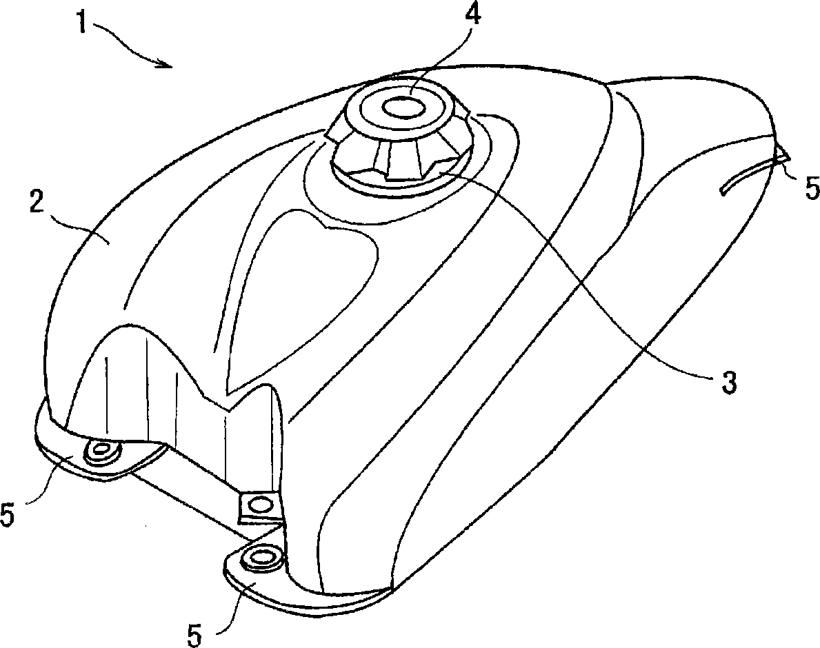
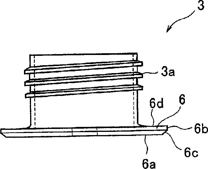
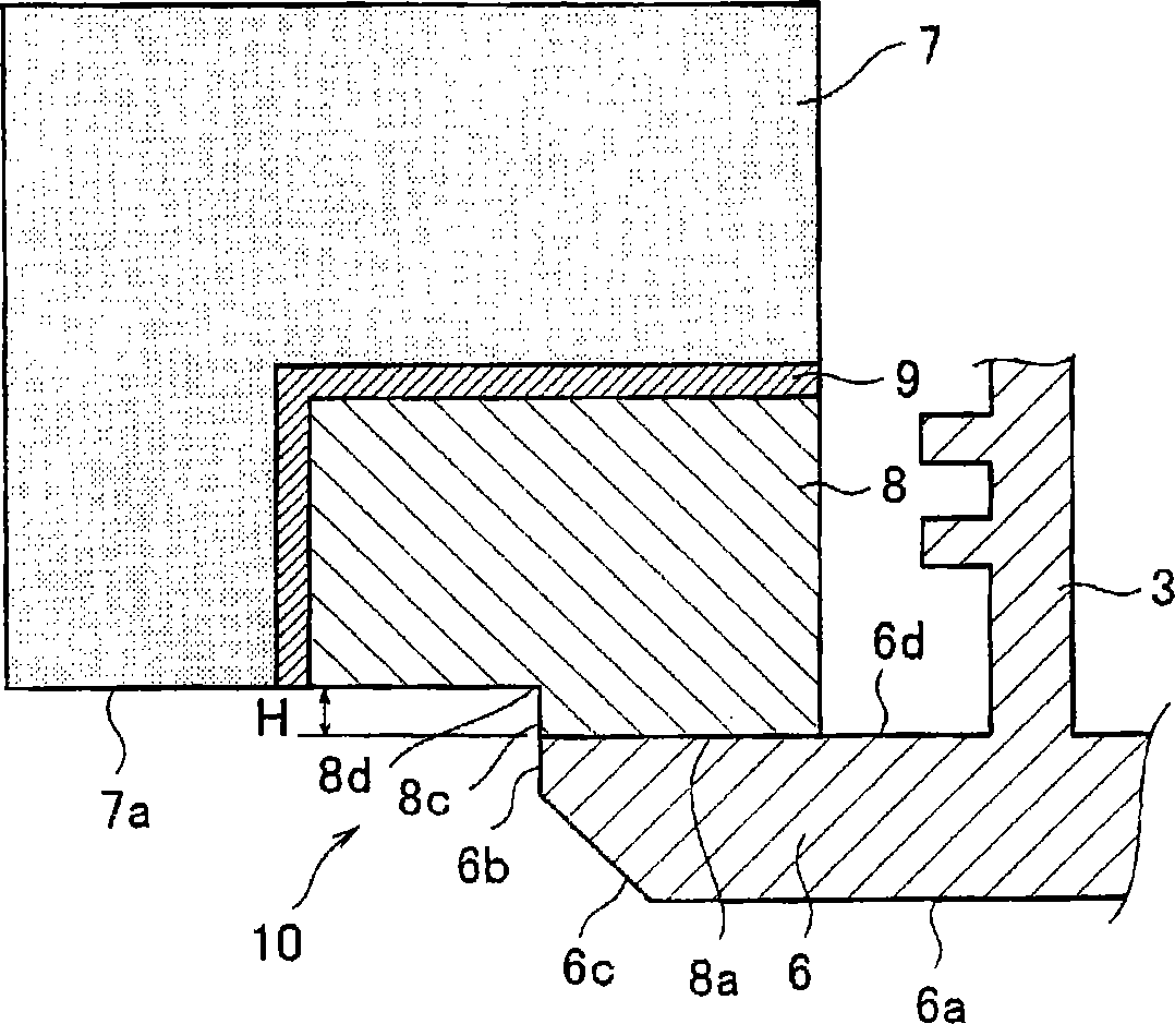
[0045] Embodiments of the present invention will be described below based on the drawings. here, figure 1 It is a perspective view of a fuel tank for a motorcycle to which the method of welding an insert member according to the present invention is applied, figure 2 is a side view of the fill port body, image 3 It is a schematic cross-sectional view of a mold structure for carrying out the first embodiment of the insert part welding molding method of the present invention, Figure 4 is an action explanatory diagram of the first embodiment, Figure 5 It is a schematic cross-sectional view of a mold structure for implementing a second embodiment of the method of welding an insert part of the present invention, Figure 6 It is an action explanatory diagram of the second embodiment.

[0046] Such as figure 1 As shown, a fuel tank 1 for a motorcycle to which the method for welding an insert of the present invention is applied has an insert member, that is, an oil filler ma...


PUM


Abstract

To provide an insert part weld molding method for reliably welding an insert part to a blow molded object while preventing an unwelded portion from being created at a circumferential edge of the insert part in a thickness direction thereof. An insert part weld molding method welds a blow molded object to an insert part 3 set in a mold 7, wherein a molding surface 7a of the mold 7 is set higher than a front surface 6d of a portion to be welded of the insert part 3, and an entire surface of a circumferential edge 6b of the insert part 3 in the thickness direction thereof and a parison 11 of the blow molded object are brought into a gapless welded state. Also adopted is a method of suppressing a decrease in temperature of the insert part 3 by arranging a preheating plate 8 which is made of a high thermal conducting material and which is to become a part of the molding surface 7a of the mold 7 in a vicinity of a portion where the parison 11 and the circumferential edge 6b of the insert part 3 in the thickness direction thereof are welded, and arranging a heat insulating plate 9 between the preheating plate 8 and the mold 7.

Description

technical field [0001] The present invention relates to an insert member welding molding method for welding various insert members to a blow molded body such as a fuel tank of a motorcycle. Background technique [0002] As a conventional welding molding method for insert parts, it is known to chamfer the peripheral part of the welding seat which is formed as a flange at the welding part of the insert part at an inclination angle, so that the welding seat is blown A method in which a molded body (fuel tank) is tightly adhered to and welded to an unfolded parison during molding (for example, refer to Patent Document 1). [0003] Patent Document 1: Japanese Patent Application No. 2003-236920 [0004] In the conventional welding molding method of an insert, the insert is placed in a mold during blow molding of a fuel tank, and the parison is welded to a welding seat of the insert in close contact with the mold when the mold is closed. [0005] However, if Figure 7 As shown,...

Claims


Application Information

Patent Timeline
Patent Type & Authority Patents(China)
IPC IPC(8): B29C49/20B29C49/48
CPCB29C2049/2095B29L2031/7172B29C2049/2026B29C2049/2017B29C49/20
Inventor 五通英三郎
Owner HONDA MOTOR CO LTD
Why Eureka
Try Eureka