Filter and manufacturing method therefor

A technology of filters and filter chambers, applied in chemical instruments and methods, fixed filter element filters, filtration separation, etc., can solve problems such as melting, product performance deterioration, unwelded parts and over-welded parts, etc., to achieve Effect of suppressing shedding, improving aesthetics, and suppressing entry into the filter chamber

Inactive Publication Date: 2010-06-09
TOYOTA BOSHOKU KK
View PDF8 Cites 0 Cited by
  • Summary
  • Abstract
  • Description
  • Claims
  • Application Information

AI Technical Summary

Problems solved by technology

[0007] However, in Patent Document 3, since the laser beam is irradiated from the pressurizing direction of the filter element, the welded part B2 is formed in the filter chamber of the casing, so due to the output of the laser light, etc., the gap between the inner wall of the casing and the edge of the filter element Foreign matter such as welding burrs may occur in the gap and the slit of the jig, and the foreign matter may remain in the filter chamber and may deteriorate the performance of the product as a filter
In addition, in order to suppress the occurrence of foreign matter such as welding burrs in the gap between the inner wall of the housing and the edge of the filter element, when the welding part is arranged at a position sufficiently far from the gap, the outside of the welding part on the housing The size of the square side becomes larger, and there is a problem that the size of the entire filter becomes larger
[0008] In addition, in the above-mentioned Patent Document 3, since the laser beam is irradiated through the slit of the fastening jig, it is difficult to secure a necessary and sufficient welded width on the welded portion.
In addition, when the slit width of the fastening jig is set to a relatively large value in order to ensure a necessary and sufficient welding width, the pressure exerted by the fastening jig on the filter element becomes weak, and the fiber density of the welding part decreases. , it is difficult to achieve reliable deposition
[0009] In addition, in the above-mentioned Patent Document 3, since it is necessary to transmit the laser light through the filter element, it is necessary to use a filter element having laser light transmittance.
[0010] In addition, in the above-mentioned Patent Document 3, since the edge portion of the filter element is exposed in the filter chamber, there is a possibility that the performance of the product may deteriorate due to the fiber etc. Adjustment so that the molten laser absorbing material saturates the entire thickness of the filter element and solidifies it. It is necessary to have a subtle adjustment function of the heat of laser irradiation that takes into account factors such as fluctuations in transmittance.
[0011] Furthermore, as a filter element, in order to enlarge the filtering surface, a pleated filter element is sometimes used, but the pleated portion becomes a complicated three-dimensional shape. Therefore, the laser cannot be irradiated vertically to the melting member (case member) on the absorption side, and the melting member cannot be reliably melted.
Furthermore, since it is difficult to adjust the focal length of the laser to the welded part along the wrinkled part, there is a risk of non-welded parts and over-welded parts (material charred parts)

Method used


Image

  • Filter and manufacturing method therefor
  • Filter and manufacturing method therefor
  • Filter and manufacturing method therefor

Examples


Embodiment 1

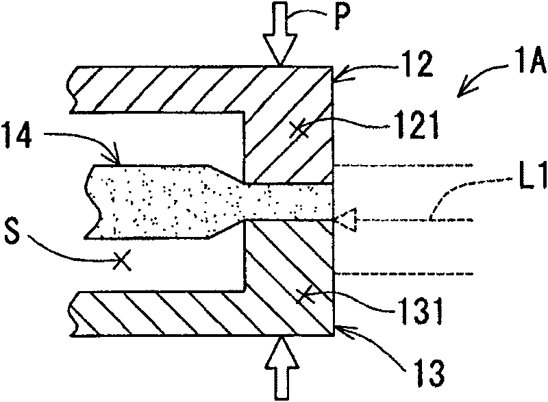
[0184] Next, the filter 1A according to the first embodiment will be described. First, the manufacturing method of this filter 1A is described, as figure 2 As shown, in the state where the edge portion of the element 14 is clamped between the butt end 121 of the upper case member 12 and the butt end 131 of the lower case member 13, each case is pushed along the butt direction P by an external force. The members 12, 13 are pressurized. At this time, the edge portion of the element 14 becomes a low-density state. Then, in this pressurized state, laser light L1 is irradiated from the side toward the outer surface of the element 14 and the outer surface of the front end side of the mating end portion 131 of the lower case member 13 .

[0185] In addition, the mounting position of the edge portion of the element 14 with respect to each case member 12 , 13 is set at a position where it is not exposed outward from the outer surface of the mating end portion 121 , 131 of each case ...

Embodiment 2

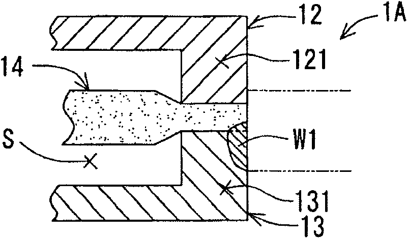
[0189] Next, the filter 1B according to the second embodiment will be described. In this filter 1B, as in Figure 4 As shown, on the upper housing member 12, an outer wall portion 124 connected to the butt end portion 121 thereof and extending in the butt direction P is provided. In addition, as in the above-mentioned first embodiment, in the state where the edge portion of the element 14 is sandwiched between the butt end portions 121, 131 of the respective case members 12, 13, the respective case members 12, 13 are pushed toward each other by external force. Pressurize in docking direction P.

[0190] At this time, the inner peripheral surface of the outer wall portion 124 abuts against the base end side outer surface of the mating end portion 131 of the lower case member 13 on the abutting surface extending along the mating direction P, and at the same time, a predetermined The gap faces the outer surface on the front end side of the mating end portion 131 of the lower ca...

Embodiment 3

[0196] Next, the filter 1C according to the third embodiment will be described. In this filter 1C, as Figure 6 As shown, similarly to the above-described second embodiment, the welded portion W1 for the element is formed by the laser L1, and the welded portion W2 for the case is formed by the laser L2 at the same time.

[0197] In the above filter 1C, such as Figure 7 As shown, a concave portion (indicated as a “fitting portion” according to the present invention) is provided on the outer wall portion 124 of the above-mentioned case member 12 . In addition, the base end side of the mating end portion 131 of the lower housing member 13 is formed in a flange shape protruding outward, and at this position, the convex portion 132 (according to In the present invention, it is referred to as "part to be mated").

[0198] The recessed portion 122 and the protruding portion 132 are arranged on the side of the filter chamber S of the casing welded portion W2. The mating width (the...


PUM


Abstract

The present invention provides a filter capable of suppressing the detachment of a filter element at the time of using the filter and suppressing the generation of foreign matters such as welding burrs inside a filter chamber. This filter 1 is provided with a first case member (upper case member 12) and a second case member (lower case member 13) forming the filter chamber S by being abutted to each other, and the filter element 14 held between the respective abutting end parts 121 and 131 of the first case member and the second case member. The first case member is laser transmissible, the second case member is laser absorptive and a welding part W1 for the element by a laser beam is formed on the outer side face side of the contact part of the abutting end part of the second case memberand the filter element.

Description

technical field [0001] The present invention relates to a filter and a manufacturing method thereof, and more specifically, to a filter capable of suppressing drop-off of a filter element and suppressing foreign matter such as welding burrs in a filter chamber during use of the filter and a manufacturing method thereof. Background technique [0002] In the past, as an oil filter for an automatic transmission, it is known that a filter element (for example, Refer to Patent Documents 1 and 2). [0003] In the above-mentioned Patent Document 1, a technique is disclosed in which the filter material 3 is compressed and fastened by the respective inner edge protrusions 1d and 2d of the upper case 1 and the lower case 2 . However, in this patent document 1, since only the filter material is compressed and fastened, when a high internal pressure is applied when the oil filter is used, the filter material may fall off. [0004] In addition, the aforementioned Patent Document 2 disc...

Claims


Application Information

Patent Timeline
Patent Type & Authority Patents(China)
IPC IPC(8): B01D29/07B29C65/16B01D35/02B29L31/14F16H57/04
CPCB29C65/16B29C66/1142B29C66/54B29C65/1635B29C65/1664B29C65/1648B29C66/5412B29C66/50B29C66/322B29C65/1677B29C65/1629B29C66/112B29C66/114B29C66/1222B29C66/1224B29C66/124B29C66/12445B29C66/12449B29C66/12469B29C66/1248B29C66/71B29C66/73772B29C66/73776B29C66/73921B29C66/8322B29C66/83221B29L2031/14
Inventor 久野哲也
Owner TOYOTA BOSHOKU KK
Why Eureka
Try Eureka