Automatically length-fixing plate shearing machine

An automatic length-fixing and shearing machine technology, which is applied in the field of forging machinery, can solve problems such as low production efficiency and easy safety accidents, and achieve the effects of improving production efficiency, avoiding coordination contradictions, and high degree of automation

Inactive Publication Date: 2011-04-13
杨焕敏
View PDF0 Cites 22 Cited by
  • Summary
  • Abstract
  • Description
  • Claims
  • Application Information

AI Technical Summary

Problems solved by technology

[0003] The purpose of the present invention is to provide an automatic fixed-length cutting shearing machine, which overcomes the defects of the existing shearing machines, such as low production efficiency and easy occurrence of safety accidents

Method used


Image

  • Automatically length-fixing plate shearing machine
  • Automatically length-fixing plate shearing machine

Examples


Embodiment Construction

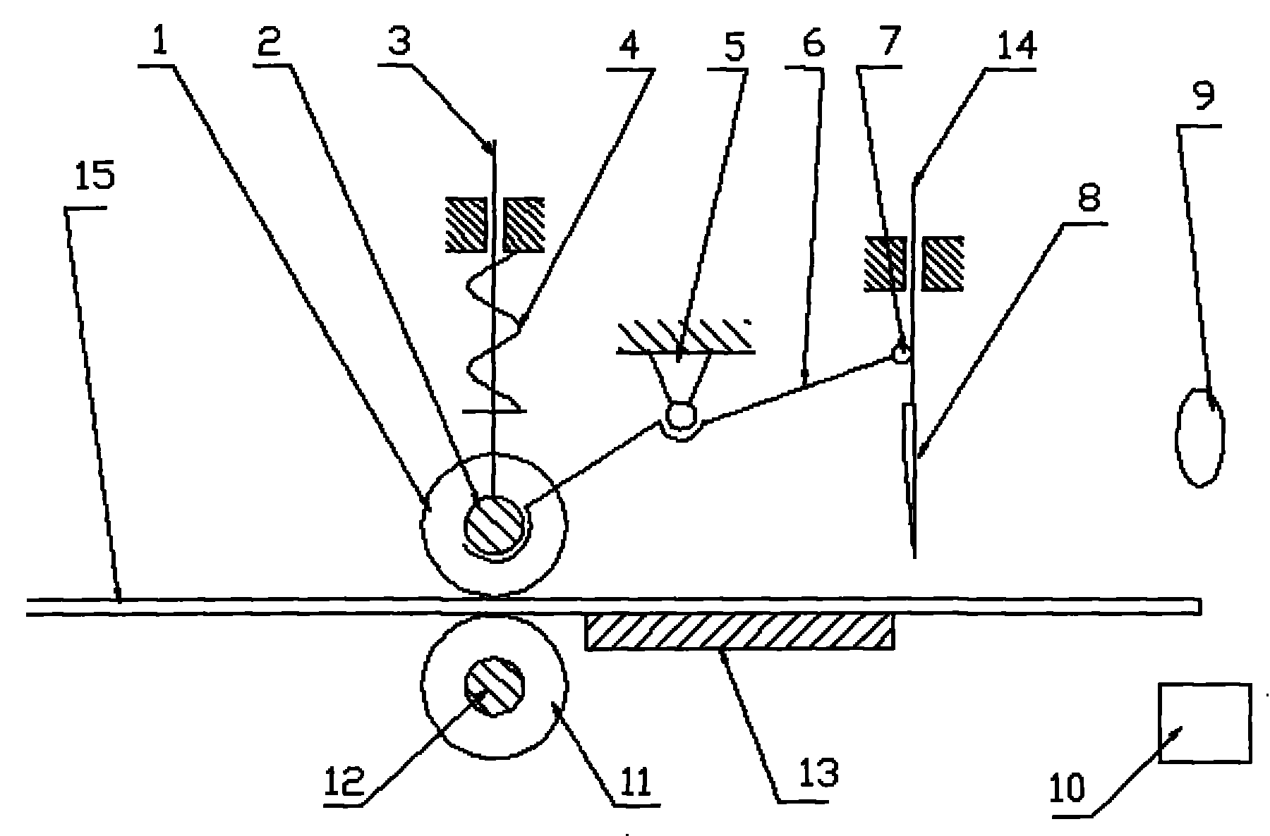
[0009] Install the pressing roller (1) on the upper surface (3) of the pressing bar through the pressing roller shaft (2), install the compression spring (3) on the pressing bar (3), and install it in the middle of the connecting rod (6) at an appropriate position On the support (5), one end of the connecting rod (6) is hinged with the pressing roller shaft (2), and the other end is hinged with the cutter seat (14) through the connecting rod pin (7), and the cutter Installed on the top of the cutter seat (14), the infrared emitting device (9) and the infrared receiving device (10) are symmetrically installed at appropriate positions on both sides of the guide rail (13). At the same time, the infrared emitting device (9) and the infrared receiving device The position of the device (10) in the guiding direction of the guide rail (13) can be adjusted. The guide rail (13) is installed and fixed on the shearing machine, and the direction of its guidance is perpendicular to the plane...


PUM


Abstract

An automatically length-fixing shearing machine is provided. A compaction roller is installed on a pressure bar by a compression roller shaft. A compression spring is installed on the pressure bar, and the proper part in the middle of a connecting rod is installed on a bearer. One end of the connecting rod is hinged to the compression roller shaft, and the other end is hinged to a cutting knife seat through a connecting rod pin. A cutting knife is installed on the cutting knife seat. An infrared ray emitter and an infrared ray receiver are installed symmetrically in proper positions of two sides of a guide rail. Simultaneously, the positions of the infrared ray emitter and receiver can be adjusted in the guiding direction of the guide rail. The guide rail is fixedly installed on the plate shearing machine, and the guiding direction of guide rail is vertical to the cutting knife plane of the plate shearing machine. A fixed roller is fixedly installed in proper position of the plate shearing machine through a fixed roller shaft, wherein the highest position of the fixed roller is in the same plane with the upper plane of the guide rail.

Description

technical field [0001] The invention relates to a shearing machine, in particular to an automatic fixed-length cutting shearing machine, which belongs to the technical field of forging machinery. Background technique [0002] At present, the main machine for cutting sheet metal is a shearing machine. In order to make the cutting of sheet metal meet certain size requirements, it is necessary to install a corresponding mechanical positioning device on the shearing machine. This positioning device is used in It needs to be adjusted in advance, and at the same time, two operators need to cooperate to complete the shearing task, that is: in the work, one of them pushes the sheet metal, and one of them measures and operates the machine; therefore, the existing shearing machine not only The production efficiency is low, and because two people are required to work in unison, once a coordination error occurs, safety accidents are prone to occur; in addition, once the cutting size of ...

Claims


Application Information

Patent Timeline
Patent Type & Authority Applications(China)
IPC IPC(8): B26D1/06B26D5/34B65H5/06
Inventor 杨焕敏
Owner 杨焕敏
Why Eureka
Try Eureka