Eureka AIR delivers breakthrough ideas for toughest innovation challenges, trusted by R&D personnel around the world.

Low-pressure pilot control high-flow superhigh-pressure hydraulic cartridge valve system

A pilot-controlled, high-flow technology, used in fluid pressure actuation devices, servo motor assemblies, mechanical equipment, etc., can solve problems such as increased design costs, deformation of cartridge valves and pilot solenoid valves, and system failures, achieving a degree of control. And the effect of high reliability and simple structure

Inactive Publication Date: 2011-04-13
SHANDONG TAIFENG INTELLIGENT CONTROL CO LTD
View PDF3 Cites 9 Cited by
  • Summary
  • Abstract
  • Description
  • Claims
  • Application Information

AI Technical Summary

Problems solved by technology

The working pressure of the existing cartridge valve system can only be used in low-medium and high-pressure working conditions. When the system experiences instantaneous or continuous ultra-high pressure, the cartridge valve and pilot solenoid valve will be deformed. lead to system failure; even simply enlarging the existing cartridge valve structure will result in a huge volume, especially the shape and structure of the pilot solenoid valve, which will increase the design cost and sometimes fail to meet the requirements, which limit the application of ultra-high pressure equipment

Method used


Image

  • Low-pressure pilot control high-flow superhigh-pressure hydraulic cartridge valve system
  • Low-pressure pilot control high-flow superhigh-pressure hydraulic cartridge valve system
  • Low-pressure pilot control high-flow superhigh-pressure hydraulic cartridge valve system

Examples


Embodiment Construction

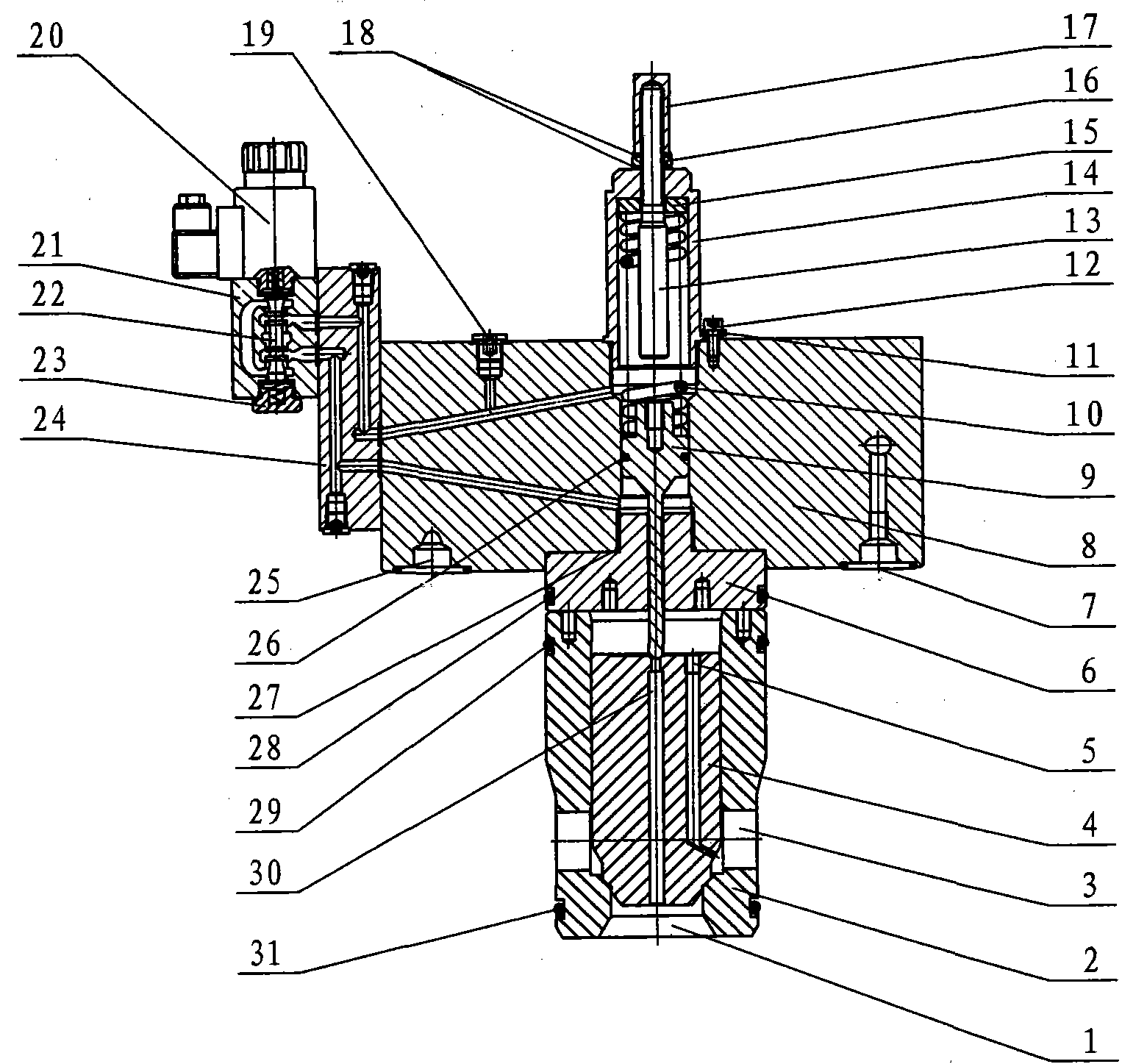
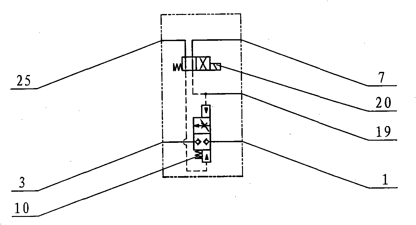
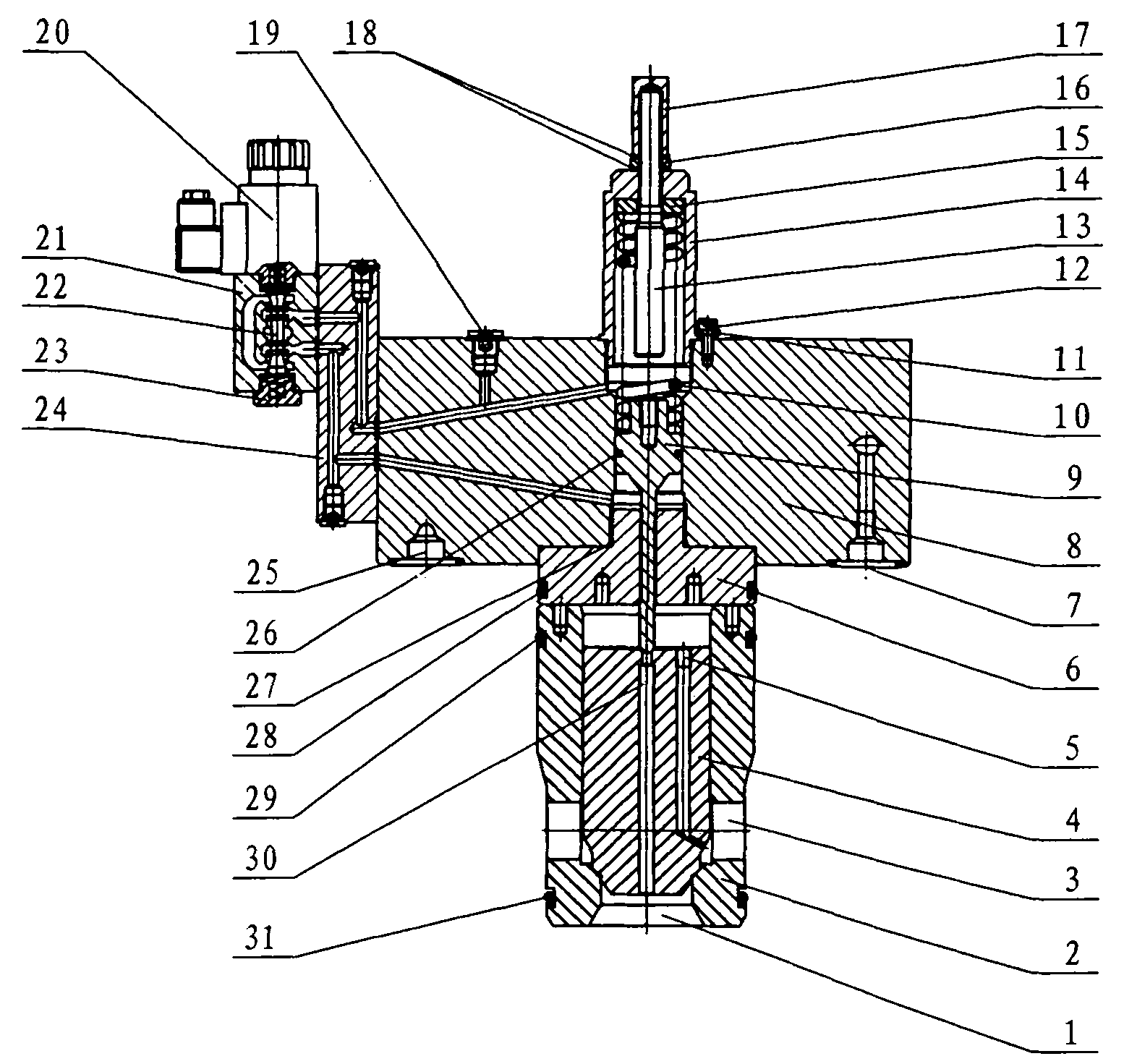
[0010] refer to figure 1 , 2 , the low-pressure pilot control large-flow ultra-high pressure hydraulic cartridge valve system of the present invention is realized by adopting the following technical scheme: it is composed of a valve sleeve 2, a main valve core 4, a pressure amplification mechanism and a pilot valve. There are main valve oil inlet 3 and main valve oil outlet 1, the main valve core 4 is installed in the axial hole of the valve sleeve 2, and the through hole 30 is set in the middle of the main valve core 4 to communicate with the main valve oil outlet 1, and the main valve One end of the core 4 is provided with a damping hole 5 to communicate with the oil inlet 3 of the main valve, a piston rod 9 is provided in the axial hole of the control cover plate 8, and a top cover 6 is provided between the piston rod 9 and the valve sleeve 2, and the raised part of the top cover 6 is rotated. Into the control cover plate 8, the piston rod 9 passes through one end of the t...


PUM


Abstract

The invention relates to a low-pressure pilot control high-flow superhigh-pressure hydraulic cartridge valve system, in particular to a low-pressure pilot control high-flow superhigh-pressure hydraulic cartridge valve system device. The system is characterized in that a master valve core is arranged in the axial hole of a valve bush; the middle of the master valve core is provided with a through hole which is communicated with the oil outlet of a master valve; a piston rod is arranged in the axial hole of a control cover plate; a top cover is arranged between the piston rod and the valve bush; the other end of the piston rod is provided with a return spring; the other end of the return spring is provided with a spring seat; the other end of the spring seat is provided with a threaded sleeve; one end of the threaded sleeve is provided with a bonded washer and a locking nut; the side face of the control cover plate is provided with a pressure tap, a control orifice and an oil return orifice; holes in a transition plate and the control cover plate are communicated with one end of the piston rod; and the other side of a pilot valve body is provided with a threaded plug. The system provided by the invention is simple in structure, can be opened instantaneously, and can be closed in a safe and reliable way; the pilot stage is controlled by low pressure to realize the superhigh-pressure control; and the system provided by the invention can be widely used in hydraulic control systems in machine tool die-casting and forging metallurgy, ships and mining.

Description

Technical field: [0001] The invention relates to a low-pressure pilot control large-flow ultra-high pressure hydraulic cartridge valve system, especially a low-pressure pilot control large-flow ultra-high pressure hydraulic cartridge valve that withstands ultra-high pressure and realizes throttling in the process of rapid hydraulic opening and safe and reliable closing. system equipment. Background technique: [0002] At present, hydraulic cartridge valves have a series of advantages such as simple structure, small flow resistance, small impact, large flow capacity, fast action, and less leakage, and are widely used in machine tools, casting and forging, die-casting, metallurgy, ships, and mining industries. The working pressure of the existing cartridge valve system can only be used in low-medium and high-pressure working conditions. When the system experiences instantaneous or continuous ultra-high pressure, the cartridge valve and pilot solenoid valve will be deformed. L...

Claims


Application Information

Patent Timeline
Patent Type & Authority Applications(China)
IPC IPC(8): F15B13/02
Inventor 于良振张春光高梅柱高彦龙任兴宋红岩
Owner SHANDONG TAIFENG INTELLIGENT CONTROL CO LTD
Why Eureka
Eureka Blog
Learn More