Piston type speed controller

A speed controller, piston-type technology, applied in auxiliary non-electrical speed/acceleration control, shock absorber, shock absorber, etc., can solve the problems of high manufacturing cost and difficult parts processing, and achieve low manufacturing cost , the effect of easy processing

Inactive Publication Date: 2011-04-13
何少敦
View PDF5 Cites 4 Cited by
  • Summary
  • Abstract
  • Description
  • Claims
  • Application Information

AI Technical Summary

Problems solved by technology

[0003] In order to overcome the shortcomings of today's piston-type speed controllers, which require an external animal flow chamber, the processing of parts is difficult and the manufacturing cost is high, the present invention proposes a piston-type speed controller, which includes a flow medium, a piston, and a piston rod. , piston cylinder, piston cylinder end and seal, the discharge hole is set on the piston, when the piston moves, the flow medium flows from one side of the piston to the other side of the piston through the discharge hole, and through the control of the discharge hole area to control the flow velocity of the medium, so as to achieve the purpose of controlling the piston speed. Therefore, the piston speed controller proposed by the present invention does not need to be equipped with an external animal flow chamber, so the parts are easy to process and the manufacturing cost is low.

Method used


Image

  • Piston type speed controller
  • Piston type speed controller
  • Piston type speed controller

Examples


Embodiment Construction

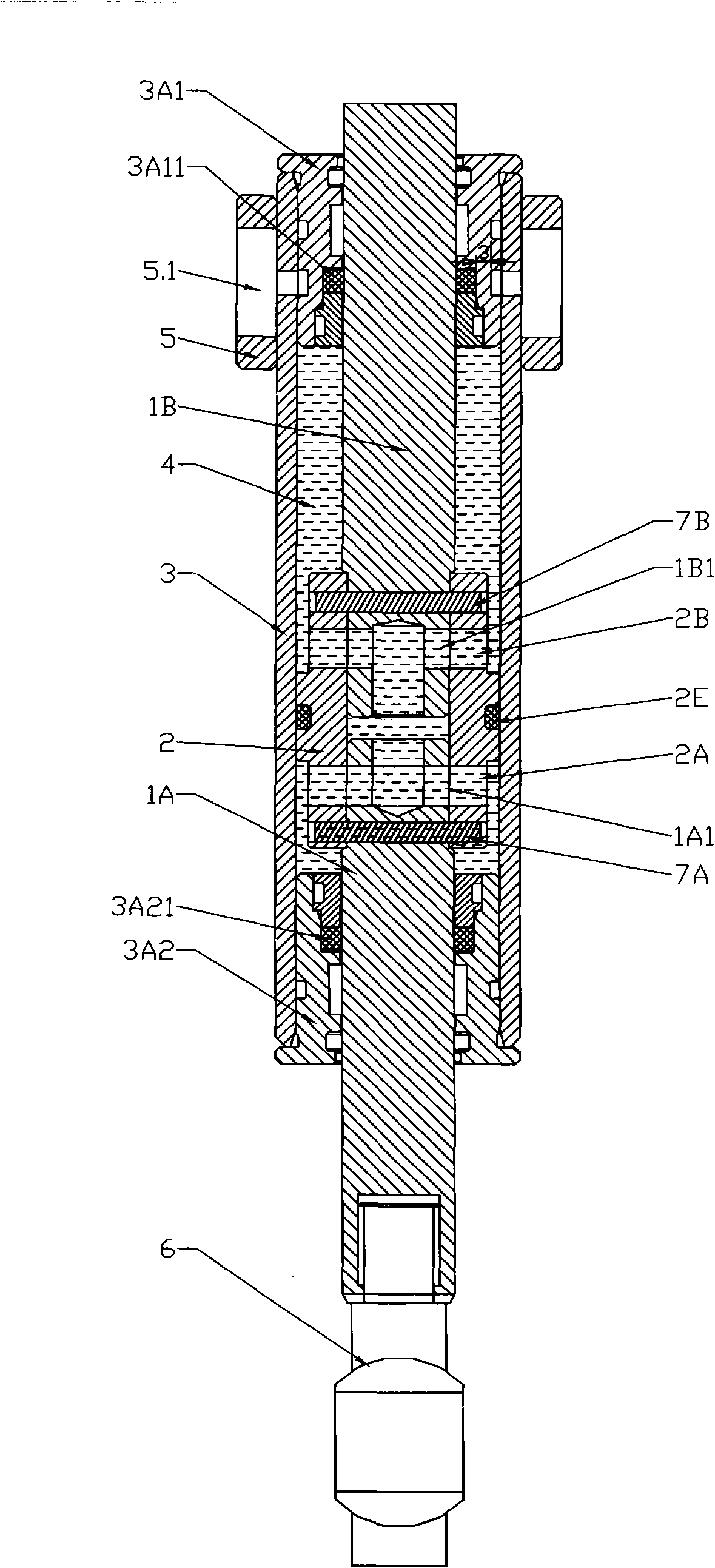
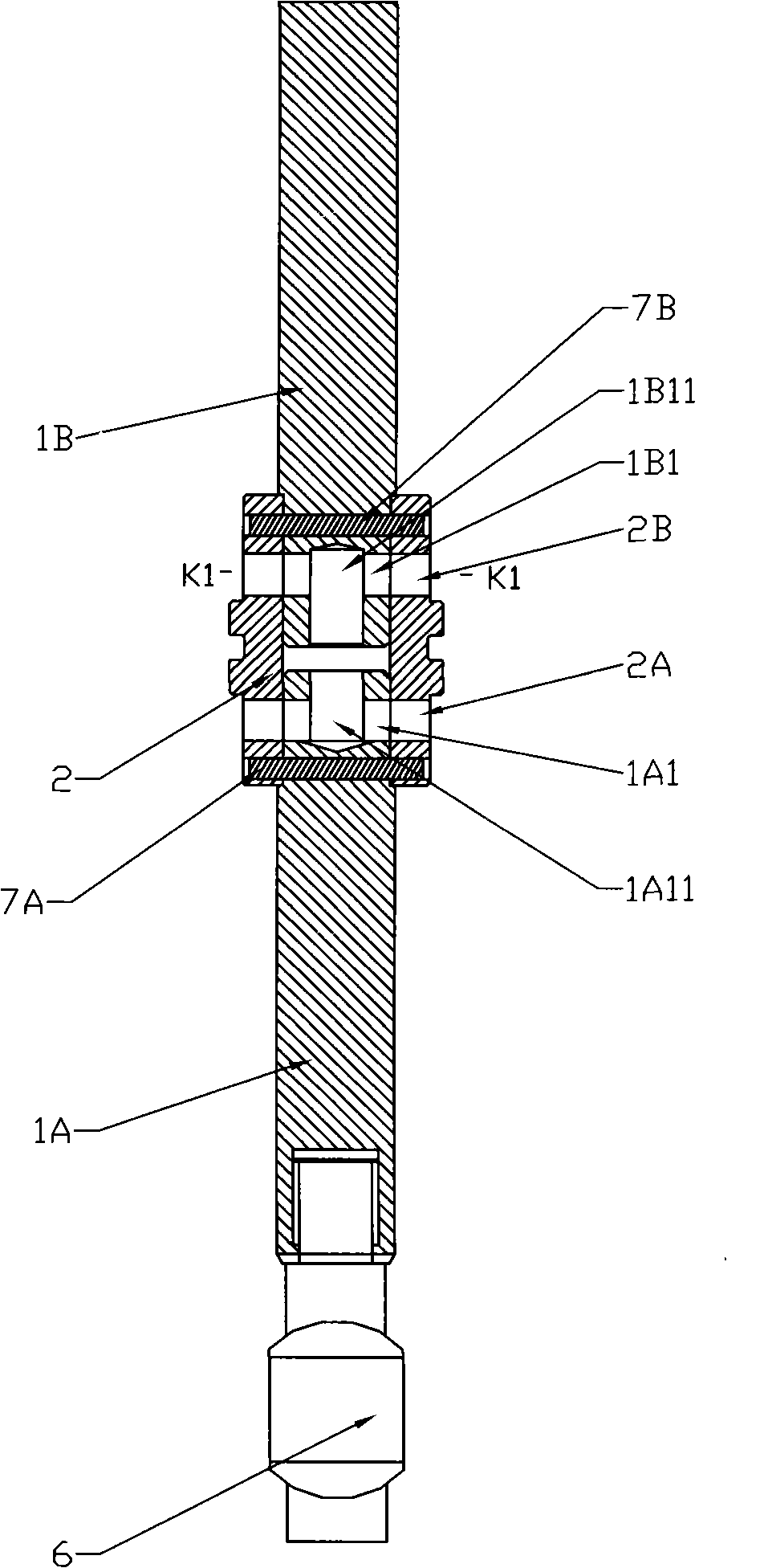
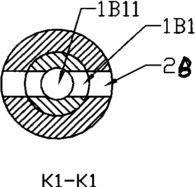
[0018] figure 1 , figure 2 , image 3 is a structural schematic diagram of the first embodiment of the present invention, figure 1 is a schematic diagram of the structure of this embodiment, figure 2 is a partial view of this embodiment, image 3 yes figure 2 The sectional view of the figure shows that, unlike the first embodiment, the piston speed controller of this embodiment mainly includes a flow medium 4, a piston 2, piston rods 1A and 1B, a piston cylinder 3, and a piston cylinder end 3A1 and 3A2, fixed seat 5, rod end connector 6 and seals 3A11, 3A21, 2E, seals 2E are arranged on piston 2, and piston 2 is connected and fixed to piston rods 1A and 1B respectively through pin shafts 7A and 7B, The piston cylinder 3 seals the flow medium 4 inside the cylinder body 3 through the two piston cylinder ends 3A1 and 3A2 arranged at both ends, the piston 2 is arranged inside the piston cylinder 3 and the piston rods 1A and 1B pass through the ends of the piston cylinder ...


PUM


Abstract

The invention relates to a piston type speed controller. In order to overcome the defects of large processing difficulty and high manufacturing cost of parts of the traditional piston type speed controller, which are caused by needing to set an outer flow storage chamber, the invention provides a piston type speed controller comprising a flowing medium, a piston, piston rods, a piston cylinder, apiston cylinder tip and a sealing member. The piston type speed controller is characterized in that the piston is provided with two piston rods, through holes or through gaps are arranged on the piston rods, and the through holes or through gaps of the two piston rods are communicated with each other to form medium circulating throttle pipelines; and when the piston is moved, the flowing medium sequentially flows into the through hole or through gap of one piston rod and then flows out and enter the other side of the piston from the through hole or through gap of the other piston rod.

Description

technical field [0001] The invention relates to a speed controller, especially a piston type speed controller. Background technique [0002] The piston speed controller controls the speed of the piston by controlling the flow rate of the medium flowing through the discharge hole. The known piston speed controller includes a flow medium, a piston, a piston rod, a piston cylinder, a piston cylinder end, an outer The animal flow chamber and the seal, the discharge hole is arranged on the piston cylinder along the length direction, when the piston moves, the flow medium flows from the piston cylinder into the outer animal flow chamber through the discharge hole or from the outer animal flow chamber into the piston cylinder, The speed of the piston is controlled by controlling the flow rate of the medium. The problem is that the current piston speed controller needs to be equipped with an external animal flow chamber, so the processing of parts is difficult and the manufacturing ...

Claims


Application Information

Patent Timeline
Patent Type & Authority Applications(China)
IPC IPC(8): G05D13/42
CPCF16F9/462F16F9/20
Inventor 何少敦
Owner 何少敦
Why Eureka
Try Eureka