Lead crimping position corrector

A wire crimping and corrector technology, applied in the directions of circuit/collector parts, connections, electrical components, etc., can solve the problems of inconvenient construction on site, lack of correction tools, bending and deformation of hydraulic joints, etc., to achieve easy operation and high quality correction. high effect

Inactive Publication Date: 2011-04-13
NANYANG POWER SUPPLY COMPANY OF STATE GRID HENAN ELECTRIC POWER
View PDF0 Cites 5 Cited by
  • Summary
  • Abstract
  • Description
  • Claims
  • Application Information

AI Technical Summary

Problems solved by technology

[0002] In the construction of power line erection projects, the length of the wires of the wire reel is often inconsistent with the length of the construction section of the line. When the length of the entire wire is still not enough for the construction, it is necessary to lengthen the wire connection. At present, the wire connection The commonly used method is hydraulic connection, and the hydraulic pipe is used for the correction of the wire and the crimping joint. However, due to the influence of a series of subjective and objective factors such as improper operation and unstable power of the hydraulic machine during the construction of the hydraulic connection, the hydraulic joint after the connection is bent. Deformation and other conditions seriously affect the construction period and project quality of the conductor erection
In the on-site construction, there is no professional and reliable correction tool after the hydraulic joint of the wire is bent. It is often used to strike with a hammer or a wooden stick for manual correction. However, the force is either too large or too small when striking. degree of damage, causing great inconvenience to the site construction

Method used


Image

  • Lead crimping position corrector
  • Lead crimping position corrector

Examples


Embodiment Construction

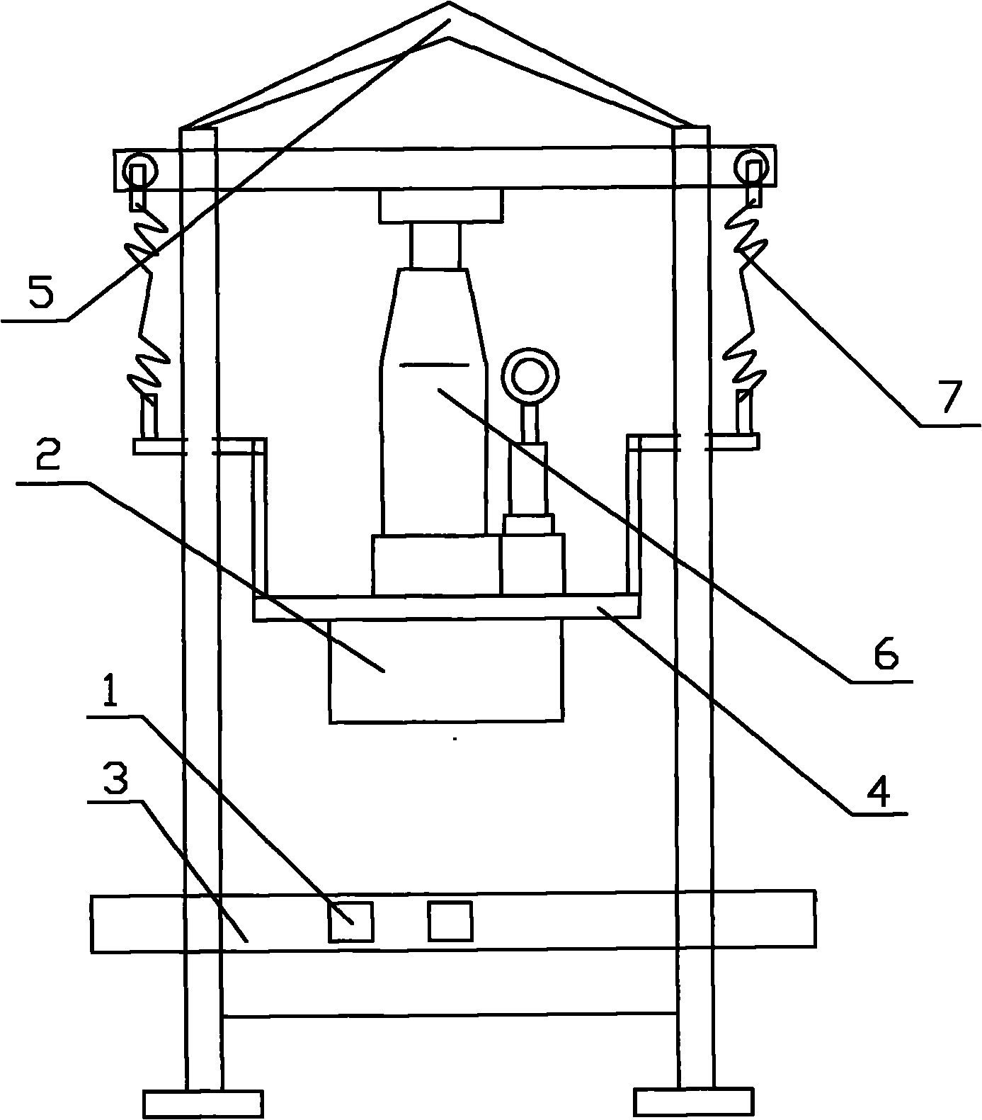
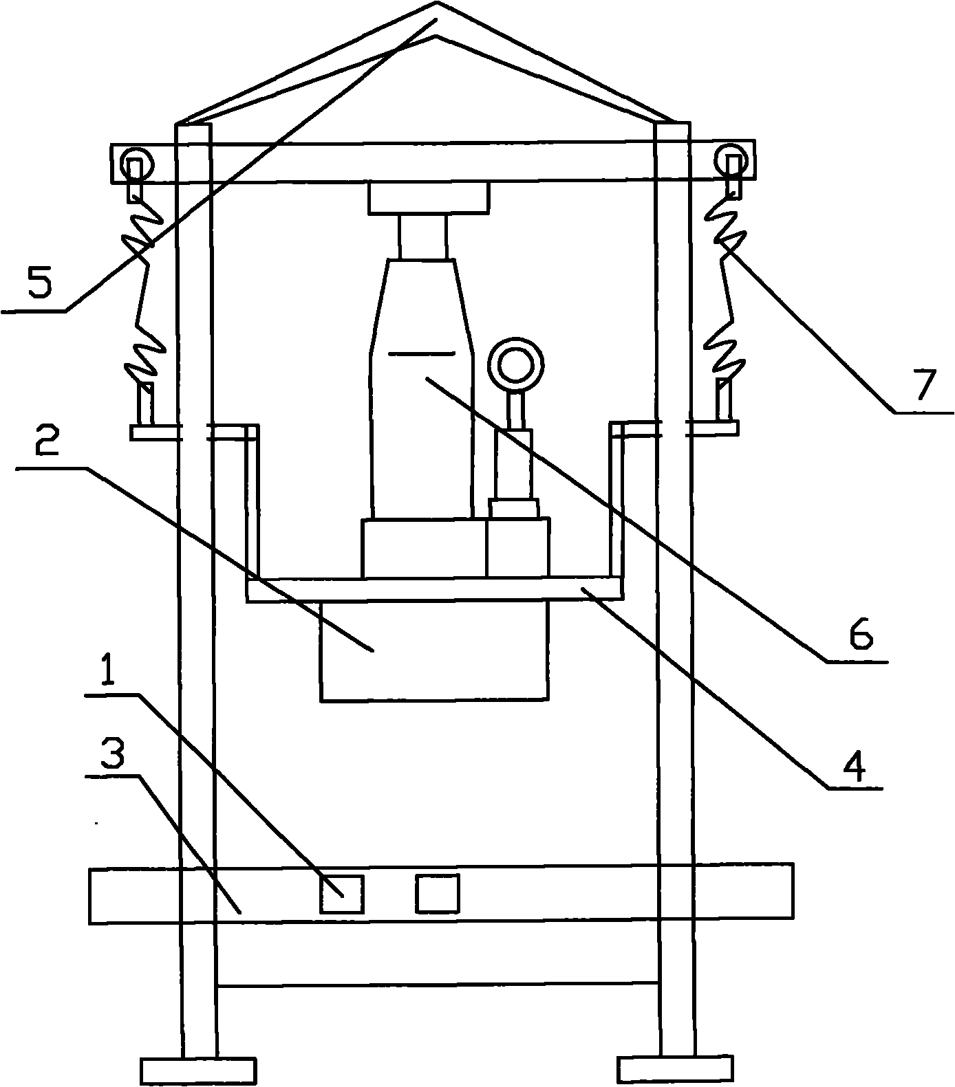
[0009] Such as figure 1 Shown: a wire crimping position corrector, including a main frame 5, a tension spring 7, an upper movable plate 4, a jack 6, an upper pressure groove 2, a lower groove 3, a movable spacer 1, the upper part of the main frame 5 An extension spring 7 is arranged on the beam, and the extension spring 7 is connected with the upper movable plate 4, the jack 6 is arranged on the upper movable plate 4, the upper pressure groove 2 is arranged on the lower movable plate 4, and the main frame The bottom of 5 is provided with lower groove 3, and described movable spacer 1 is the block that can move freely.

[0010] When in use, put the movable pad 1 into the lower groove 3, adjust the distance between the two movable pads 1 according to the type of wire or the degree of bending to make it in a suitable position, and then put it into the crimped and bent wire. Make the curved back of the wire face upward, and shake the jack 6 with the operating rod to move the uppe...


PUM


Abstract

The invention discloses a lead crimping position corrector. The corrector comprises a main body frame, a pull spring, an upper movable plate, a jack, an upper pressure groove, a lower groove and a movable cushion block, wherein an upper beam of the main body frame is provided with the pull spring; the pull spring is connected with the upper movable plate; the jack is arranged on the upper part of the upper movable plate; the upper pressure groove is formed on the lower part of the upper movable plate; and the lower part of the main body frame is provided with the lower groove. A bend and deformed lead is arranged between two movable cushion blocks of the lower groove, so that correcting effect can be achieved under the action of a back pressure produced by operating the jack. The corrector is easy and convenient to operate because only the jack needs to be operated after a crimped and bent lead is placed in position, does not damage the lead or a crimping head, achieves high correcting quality and saves time and labor.

Description

technical field [0001] The invention belongs to the technical field of electric power construction tools, and in particular relates to a wire crimping position corrector. Background technique [0002] In the construction of power line erection projects, the length of the wires of the wire reel is often inconsistent with the length of the construction section of the line. When the length of the entire wire is still not enough for the construction, it is necessary to lengthen the wire connection. At present, the wire connection The commonly used method is hydraulic connection, and the hydraulic pipe is used for the correction of the wire and the crimping joint. However, due to the influence of a series of subjective and objective factors such as improper operation and unstable power of the hydraulic machine during the construction of the hydraulic connection, the hydraulic joint after the connection is bent. Deformation and other conditions seriously affect the construction pe...

Claims


Application Information

Patent Timeline
Patent Type & Authority Applications(China)
IPC IPC(8): H01R43/00
Inventor 田培新向峰李兵
Owner NANYANG POWER SUPPLY COMPANY OF STATE GRID HENAN ELECTRIC POWER
Why Eureka
Try Eureka