Led lighting device and illumination apparatus

A technology for lighting devices and lighting devices, which is applied to lighting devices, components of lighting devices, and lamp circuit layout, etc., which can solve problems such as insufficient damping, limited resistance value, flickering of LED brightness, etc., and reduce heat generation and power consumption Effect

Active Publication Date: 2011-04-13
TOSHIBA LIGHTING & TECH CORP
View PDF3 Cites 19 Cited by
  • Summary
  • Abstract
  • Description
  • Claims
  • Application Information

AI Technical Summary

Problems solved by technology

[0003] (1) When the LED is lit at a low current level (level), the self-holding current of the phase control element of the dimmer cannot be ensured, so the brightness of the LED will flicker
That is, when the LED is turned on with the same luminance, the current flowing through the LED is smaller than the current flowing through the incandescent bulb. Therefore, the current flowing through the LED cannot ensure the self-holding current of the necessary phase control element.
[0004] (2) In order to turn on the phase control element with the expected phase, the dimmer includes a timer circuit (timer circuit) composed of a time constant circuit, but it cannot start from the moment the AC power is turned on, Supply the timing circuit operating current for operating the timing circuit to the dimmer
It is known that there is a problem that if the high-frequency vibration is a negative current for a short period of time, and the current peak value (peak value) is higher than the inherent arc-extinguishing current of the phase control element, it will not turn off (turn off)
Although the resistance value of the damping resistor is determined a

Method used


Image

  • Led lighting device and illumination apparatus
  • Led lighting device and illumination apparatus
  • Led lighting device and illumination apparatus

Examples


Example Embodiment

[0044] In order to further explain the technical means and effects of the present invention to achieve the intended purpose of the invention, in conjunction with the accompanying drawings and preferred embodiments, the specific implementation, structure, features and characteristics of the LED lighting device and the lighting device proposed in the present invention Its efficacy is described in detail later.

[0045] Reference Figure 1 to Figure 3 The first embodiment will be described.

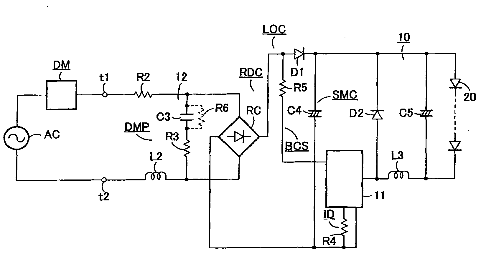
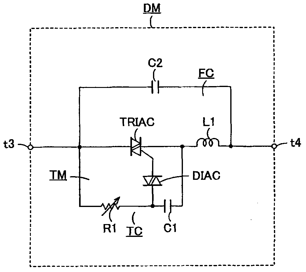
[0046] Such as figure 1 As shown, the LED lighting device includes a pair of input terminals t1, t2, a damping circuit DMP, and an LED lighting circuit LOC. The input terminals t1, t2 are connected to an AC power source AC via a dimmer DM, and LED20 is connected to the output of the LED lighting circuit LOC. End to light up the LED20.

[0047] The pair of input terminals t1 and t2 are input terminals of the LED lighting device, and are connected in series to an alternating current power source AC...


PUM


Abstract

The present invention provides an LED lighting device and an illumination apparatus, wherein the LED lighting device includes a pair of input terminals to which AC voltage is input, the AC voltage being phase-controlled by a dimmer for phase-controlling AC voltage of an AC source; a damping circuit which has a resistor inserted to a position, into which input current flows from the AC source via the dimmer in series, and a capacitor and an inductor which form a closed circuit together with the AC source and the dimmer, and suppresses high-frequency vibration generated in the dimmer when a phase control element of the dimmer is turned on; and an LED lighting circuit which rectifies AC voltage phase-controlled and input via the pair of input terminals, converts DC output voltage, which is obtained by rectification, so that the voltage adapts to a load, and lights the LED. The illumination apparatus includes an illumination apparatus body, an LED lighting device and an LED.

Description

technical field [0001] The present invention relates to an LED lighting device and a lighting device in the technical field of lighting, in particular to a dimmable light emitting diode (Light Emitting Diode, LED) lighting device and a lighting device including the LED lighting device. Background technique [0002] A two-wire phase control type dimmer using a phase control element such as a triac is widely used as a dimmer for an incandescent light bulb. Therefore, if the dimmer can be used to dim the LED, it is possible to realize a low-power dimming-compatible lighting system by simply replacing the light source without replacing existing equipment or wiring. , so it is very convenient, but actually there are the following problems. [0003] (1) When the LED is turned on at a low current level (level), the self-holding current of the phase control element of the dimmer cannot be ensured, so the brightness of the LED flickers. That is, when the LED is turned on with the s...

Claims


Application Information

Patent Timeline
IPC IPC(8): H05B37/02F21S2/00F21V23/00F21Y101/02H05B44/00
CPCH05B33/0815H05B33/0809H05B45/3575H05B45/375
Inventor 大武寛和浅见健一
Owner TOSHIBA LIGHTING & TECH CORP
Why Eureka
Try Eureka