Tool for turning/turn broaching or external milling of work pieces

A workpiece turning and tool technology, applied in the direction of milling cutting inserts, milling cutters, broaches, etc., can solve the problem of inability to adjust the position of cutting inserts

Active Publication Date: 2011-04-13
KENNAMETAL INC
View PDF1 Cites 7 Cited by
  • Summary
  • Abstract
  • Description
  • Claims
  • Application Information

AI Technical Summary

Problems solved by technology

[0004] The device described in German patent application 10 2007 013 153.6 and mentioned at the opening has the disadvantage that the position of the cutting inserts cannot be adjusted

Method used


Image

  • Tool for turning/turn broaching or external milling of work pieces
  • Tool for turning/turn broaching or external milling of work pieces
  • Tool for turning/turn broaching or external milling of work pieces

Examples


Embodiment Construction

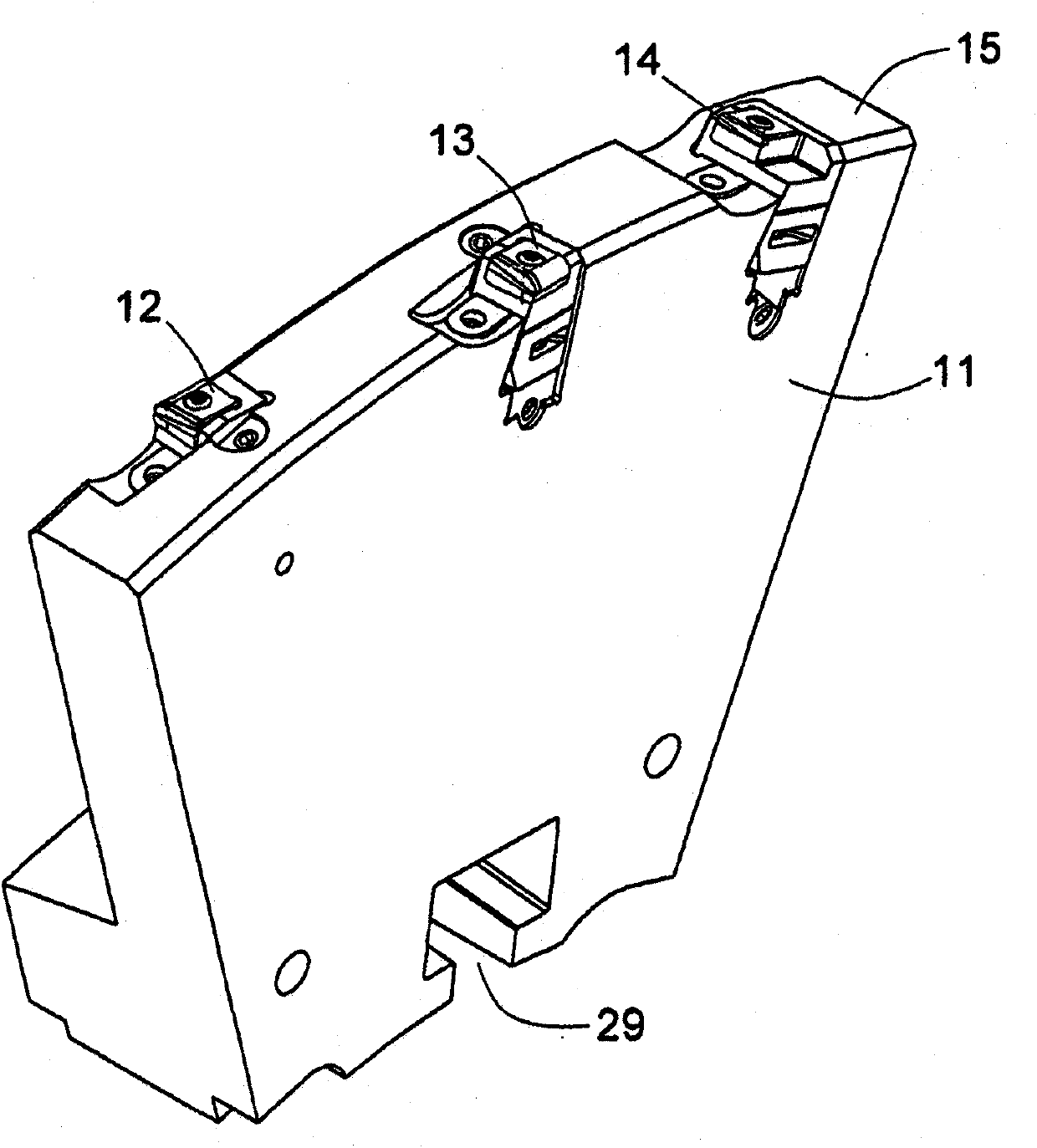
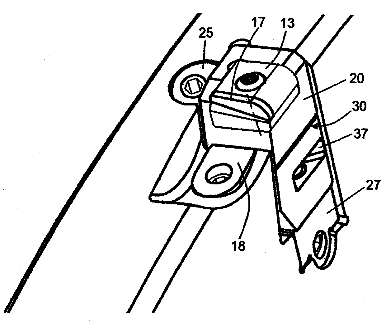
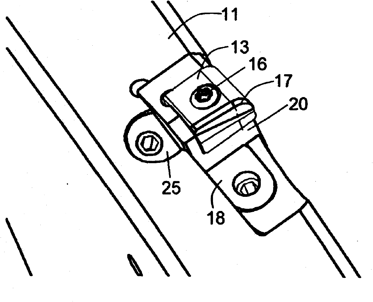
[0021] figure 1 Shown is a sector-shaped tool holder 11 having in its lower region an open slot-like recess 29 which is blind at one end and provides a stop point for the screw shank at its end . Clamping wedges are provided for axially clamping the sector 11 on a shaft (not shown). A plurality of segments 11 may be fastened side by side by suitable clamping members and thus may be fixed to form a complete ring around an existing shaft. Instead of segments 11 , it is also possible to fasten a one-piece ring body to a shaft. A plurality of cutting inserts, in this case clamped tangentially in place, are arranged peripherally in corresponding cassettes. exist figure 1 In , one cutting insert 12 is fastened laterally to the left, one cutting insert 13 is fastened laterally to the right and one cutting insert 14 is fastened centrally on the periphery 15 of the section. Such an embodiment is described in detail in German patent application 102007013153.6. Cutting inserts 12 a...


PUM


Abstract

The invention relates to a tool for turning / turn broaching or external milling of work pieces rotating about longitudinal axes during machining, comprising a disc-shaped tool support having cassettes (20) disposed peripherally thereon, each of said cassettes containing a cutting insert (12, 13, 14), said cassettes being fastenable to a circular, partially circular or segmented removable support (11) that is fastened either directly to a machine spindle or indirectly to a machine spindle by way of an adapter. According to the invention, the cassette (20) comprises a plate seat with a seating surface (21) and two lateral surfaces (22, 23) as contact surfaces for the cutting insert (12, 13, 14) and can be radially adjusted by way of an adjustment member (27) and can be fastened by way of a clamping member (18); the cassette (20) further comprises a slit-shaped groove (30) parallel to the seating surface (21) for the cutting insert (12, 13, 14), said groove having opposing groove walls with a distance and angle with respect to one another that are adjustable by way of an adjustment screw (33) such that the angular position of the seating surface (20) can be changed.

Description

technical field [0001] The invention relates to a tool for turn-turn broaching or external milling of workpieces that rotate about their longitudinal axis during machining, the tool comprising a disc-shaped tool holder with a plurality of clips arranged peripherally holders, each fitted with a cutting insert, and fastened to an annular or partly annular or sector-shaped bracket detachably or directly fastened to a machine shaft or It is indirectly fastened to a machine shaft via an adapter. Such a tool is described in German patent application 10 2007 013 153.6. Background technique [0002] Furthermore, tools are known from the prior art which have a plurality of setting devices by means of which an axial and / or radial adjustability of the cutting insert is possible. See, for example, DE 10 2006 024 880 A1 in this regard, in which a setting device with an at least substantially L-shaped profile in cross-section rests on a preferably substantially parallelepiped-shaped cut...

Claims


Application Information

Patent Timeline
IPC IPC(8): B23C5/08B23C5/24B23D43/06B23C3/06B23C3/08
CPCB23C5/2486B23C2215/20B23D37/005B23C5/2489B23C5/2462B23C5/241B23C2200/367B23C2215/16B23D43/06B23C5/2234B23C5/2472B23C5/08Y10T407/1912Y10T407/1918Y10T407/1928B23C5/24B23C5/2226
Inventor J·贝尔M·海因洛特R·弗洛伊杰J·韦尔纳
Owner KENNAMETAL INC
Why Eureka
Try Eureka