A lighting system

A lighting system and light guide plate technology, applied in the field of lighting systems, can solve problems such as not meeting the dazzling requirements

Inactive Publication Date: 2011-04-13
KONINK PHILIPS ELECTRONICS NV
View PDF1 Cites 1 Cited by
  • Summary
  • Abstract
  • Description
  • Claims
  • Application Information

AI Technical Summary

Problems solved by technology

For example, glare requirements and / or conditions for indirect and direct lighting may not be met

Method used


Image

  • A lighting system
  • A lighting system
  • A lighting system

Examples


Embodiment Construction

[0034] Throughout the description below, like reference numerals have been used, where applicable, to refer to like elements, parts, items or features.

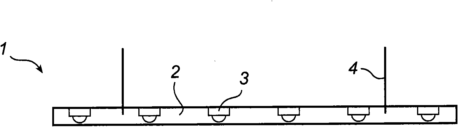
[0035] figure 1 A prior art lighting system as described above is shown.

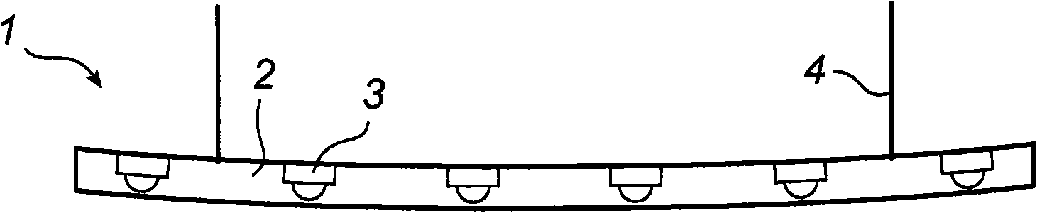
[0036] exist figure 2 is shown in the suspension as described above under the figure 1 state-of-the-art lighting system.

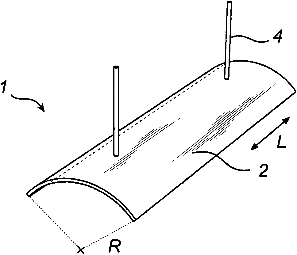
[0037] compared to image 3 , demonstrating an example embodiment of a lighting system according to the invention. The dimensions of the lighting system are typically 100x20cm and the thickness is approximately 5mm. The light emitting surface is thus approximately 100x20 cm. The lighting system 1 includes a light guide plate 2 incorporating a plurality of LEDs 3 . The LEDs are arranged to face a direction along a normal to the light guide plate.

[0038] In a preferred alternative example of the lighting system according to the invention, the LEDs are arranged to face in a direction along the longitudinal axis of the light...


PUM


Abstract

The present invention relates the field of illumination devices, in particular to a lighting system (1) comprising an elongated light guiding plate (2), comprising at least one light source (3). The light source (3) is enclosed in the light guiding plate (2). Furthermore, the light guiding plate (2) has at least one curvature (R).

Description

technical field [0001] The invention relates to the field of lighting equipment, in particular to a lighting system comprising an elongated light guide plate. Background technique [0002] In the field of lighting for indoor and outdoor use, there is an increasing need to integrate lighting systems as unobtrusively as possible. This enables architects and interior designers to use lighting to create a style that clearly distinguishes one building from another, or one room from another. Commonly used fluorescent lamp holders usually have a thickness of about 5 cm. However, it is expected that these fluorescent light fixtures will be replaced by thin LED-based lighting systems in the not-too-distant future. Many of these lighting systems typically have a thickness of less than 10mm. [0003] In office environments, it is often desirable to provide direct lighting for workspaces and indirect lighting to provide general lighting. Light fixtures with indirect and direct light...

Claims


Application Information

Patent Timeline
Patent Type & Authority Applications(China)
IPC IPC(8): G02B6/00F21S10/00
CPCG02B6/0073G02B6/0021F21S8/06
Inventor S·M·弗布鲁C·J·雅林克
Owner KONINK PHILIPS ELECTRONICS NV
Why Eureka
Try Eureka