Disc device with shutter to block insertion of a disk

a disc device and shutter technology, applied in the field of disc devices, can solve the problems of affecting the reading/writing of data from/in the disc, the risk of critical damage, and the inability to view the disc, so as to achieve stable operation, stable state, and high mechanical hardness

Inactive Publication Date: 2011-05-03
TEAC CORP
View PDF8 Cites 2 Cited by
  • Summary
  • Abstract
  • Description
  • Claims
  • Application Information

AI Technical Summary

Benefits of technology

[0036]In accordance with the present invention, a shutter mechanism is given higher mechanical hardness. Accordingly, even if a disc inserted impinges thereon, it can retain a stable state. In addition, the configuration for actuating the shutter mechanism does not include any element that causes a sliding contact resistance. Accordingly, it is possible to achieve stable operation with no variation over time and provide the mechanism with higher reliability. Further, it is possible to reduce the stroke of driving the shutter and accordingly thin the disc device.

Problems solved by technology

In addition, if a shield member is provided to prevent dusts from entering, it is made quite impossible to view the disc.
In the disc device of the slot-in type thus configured, even if the disc housed inside the device is being driven, another disc may be erroneously inserted into the slot.
In such the case, the outer rims of both the discs contact each other to lower the rotation speed of the driven disc, leaving a risk of critical damages imposed on reading / writing data from / in the disc.
This is not a suitable arrangement for seeking stable operation with no variation overtime.
Accordingly, the shutter is cantilevered and the structural hardness can not be enhanced.
Thus, the structure becomes unstable such that it easily tumbles when the disc D impinges thereon as shown in FIG. 54 and damages the rim of the disc D as a malfunction.
Such the malfunction is a problem that may arise even in a disc device configured to drive only the large diameter disc D1.

Method used


Image

  • Disc device with shutter to block insertion of a disk
  • Disc device with shutter to block insertion of a disk
  • Disc device with shutter to block insertion of a disk

Examples


Embodiment Construction

[0092]The embodiment of the present invention will now be described below as an example of a disc device configured to drive different large / small diameter discs though a disc device configure to drive only the large diameter disc also becomes a target to be implemented.

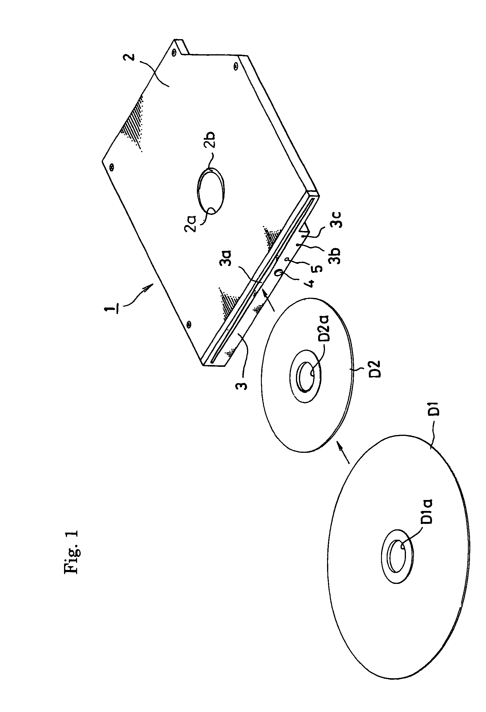
[0093]FIG. 1 shows an outward appearance of a disc device 1 of the slot-in type implementing the present invention, which includes a chassis case 2 configured shielded and having an aperture 2a formed through the center of a top plate. A protrusion 2b is formed at the rim of the aperture 2a and protruding into the inside. The chassis case 2 has a front end to which a front bezel 3 is secured. A slot 3a is formed through the front bezel to insert a 12 cm disc (hereinafter referred to as a large diameter disc) D1 and an 8 cm disc (hereinafter referred to as a small diameter disc) D2 therethrough. Through-holes 3b, 3c for emergency release are also formed through the front bezel 3. The front bezel 3 is provided with a p...


PUM

PropertyMeasurementUnit
distanceaaaaaaaaaa
diameteraaaaaaaaaa
diameteraaaaaaaaaa

Abstract

A disc device has a plurality of arms configured to support the outer rim of a disc carryable. Automatic loading is applied such that the disc inserted can be carried in the device, and the disc housed inside the device can be carried out of the device. A pair of shutter pieces are located on the central portion of a slot in a front bezel to be used to insert the disc therethrough and are spaced at a certain interval. The shutter piece rotates about one end thereof to raise / tumble the other end thereof. The tumbled shutter piece changes to the raised state after the disc is housed in the device while the shutter piece changes to the tumbled state before the disc housed inside the device is carried out of the device.

Description

BACKGROUND OF THE INVENTION[0001]1. Field of the Invention[0002]The present invention relates to a disc device configured to drive optical discs (such as CD-R / RW, DVD-R / -RW / RAM / +R / +RW) that serve as record media to record mass information in information instruments such as various computer systems.[0003]2. Description of the Related Art[0004]In general, a disc device contained in a personal computer or the like is usually provided with a disc tray to load a disc therein and configured such that the disc tray moves forward and backward. The disc loaded in the disc tray is driven within a body of the disc device to record and reproduce information.[0005]On the other hand, a disc device of the slot-in type is widely employed as the disc-trayless type. This tendency is suitable for thinning and downsizing the personal computer. The disc device of the slot-in type does not employ any disc tray to carry the disc in (load) / out of (unload) the device body. Therefore, after an operator inser...

Claims


Application Information

Patent Timeline
Patent Type & Authority Patents(United States)
IPC IPC(8): G11B17/04G11B33/12
CPCG11B17/051
Inventor FUJISAWA, SHINICHIYOKOTA, KAZUO
Owner TEAC CORP
Why Eureka
Try Eureka