Inductive power providing system

A power supply system, a technology for inducting power, applied in circuits, inductors, electric heating devices, etc., to solve problems such as being unsuitable for changing requirements, electric shocks, and limiting the number of sockets

Inactive Publication Date: 2011-04-13
POWERMAT TECHNOLOGIES
View PDF7 Cites 9 Cited by
  • Summary
  • Abstract
  • Description
  • Claims
  • Application Information

AI Technical Summary

Problems solved by technology

However, children sometimes insert pencils, pins, or other objects into the holes, sometimes with fatal results
Water can also cause a short circuit and possible electric shock
[0010] Because out

Method used


Image

  • Inductive power providing system
  • Inductive power providing system
  • Inductive power providing system

Examples


Embodiment approach

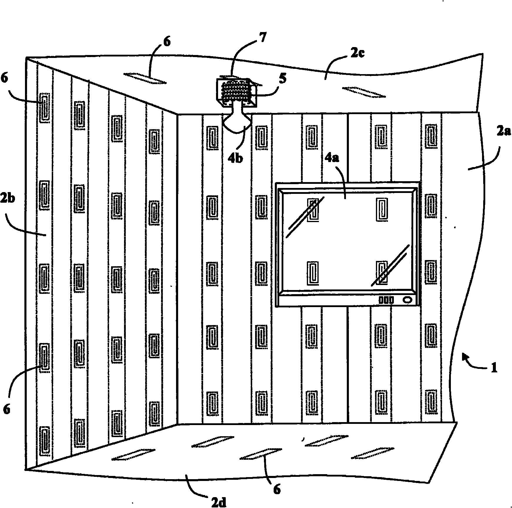
[0123] According to various embodiments of the invention, inductive power outlets may be integrated into prefabricated building materials. refer to figure 2 , shows a gypsum board panel 100 according to one embodiment of the invention. The gypsum board panel 100 comprises a layer 102 of building material, such as plaster or the like, sandwiched between facing boards 104, 106, typically of paper. Built into the plasterboard panel 100 are one or more primary inductors 108A-F and connection wires 110, 112 extending to the edge of the panel 100, allowing it to be connected to a mains power supply (not shown).

[0124] If larger, primary inductors 108A-F may be embedded within building material 102 . It should be understood, however, that primary inductors, such as induction coils 108A-F, may be relatively thin and thus may simply be glued or snapped onto face 104 , which is designed as the exterior surface of panel 100 .

[0125] Primary inductors 108a-f and wires 110, 112 may...


PUM


Abstract

A system, for providing power to a workspace by induction, comprises at least one inductive power outlet incorporated into a bounding surface of the workspace. The inductive power outlet comprises at least one primary inductor connectable to a power supply via a driver. The driver provides an oscillating voltage supply to the primary inductor and the primary inductor may inductively couple with a secondary inductor wired to an electric load.

Description

technical field [0001] The present invention relates to providing an inductive power supply system. In particular, the invention relates to the integration of inductive power outlets into the boundary surfaces of the workspace. Background technique [0002] Where and when power is supplied is an important consideration when constructing buildings. The number and location of power outlets required for each room depends on how the room is used. Often, but during construction, the function of the room's furniture is not yet known. Therefore, it is often necessary to set the location of the electric energy outlet after the construction of the building is completed, which increases the expenditure cost. [0003] Conventionally, electrical power outlets are typically placed at strategic points around the walls of a room. A ring bus connection to the power base is available. The ring bus is typically run around conductive pipes embedded in the wall, and electrical boxes on or ...

Claims


Application Information

Patent Timeline
IPC IPC(8): H01F38/14
CPCH01F38/14H01F17/0006H05B6/1236H02J5/005H01F5/003H02J50/402H02J50/90H02J50/10H02J7/0042H02J7/0047H02J50/12H02J50/40
Inventor 约西·阿藏科阿米尔·本-沙洛姆奥拉·格林沃尔德阿里克·罗费
Owner POWERMAT TECHNOLOGIES
Why Eureka
Try Eureka