
Method and device for artifact detection

A detection method and projection data technology, applied in computerized tomography scanners, echo tomography, etc., can solve the problems of reducing the speed and accuracy of artifact detection, missing artifacts, and slow artifact detection speed, so as to ensure image processing Speed, the effect of improving detection speed and accuracy

Active Publication Date: 2011-04-20
SIEMENS SHANGHAI MEDICAL EQUIP LTD
View PDF3 Cites 12 Cited by
  • Summary
  • Abstract
  • Description
  • Claims
  • Application Information

AI Technical Summary

Problems solved by technology

[0004] It can be seen that in the prior art, artificial observation is relied on to detect artifacts, which may make the detection speed of artifacts relatively slow, and may even miss artifacts, thereby reducing the detection speed of artifacts and precision

Method used


Image

  • Method and device for artifact detection
  • Method and device for artifact detection
  • Method and device for artifact detection

Examples


Embodiment Construction

[0025] In order to make the object, technical solution and advantages of the present invention clearer, the present invention will be further described in detail below with reference to the accompanying drawings and examples.

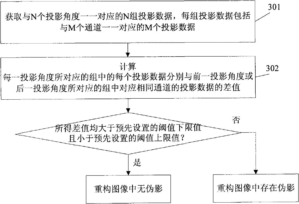
[0026] image 3 It is a flowchart of an artifact detection method according to an embodiment of the present invention. Such as image 3 As shown, the method includes the following steps:

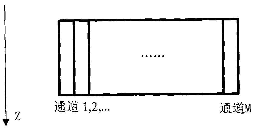
[0027] Step 301: Obtain N sets of projection data corresponding to N projection angles one-to-one according to the reconstructed image, each set of projection data includes M projection data corresponding to M channels one-to-one, where N and M are both greater than 1 positive integer.

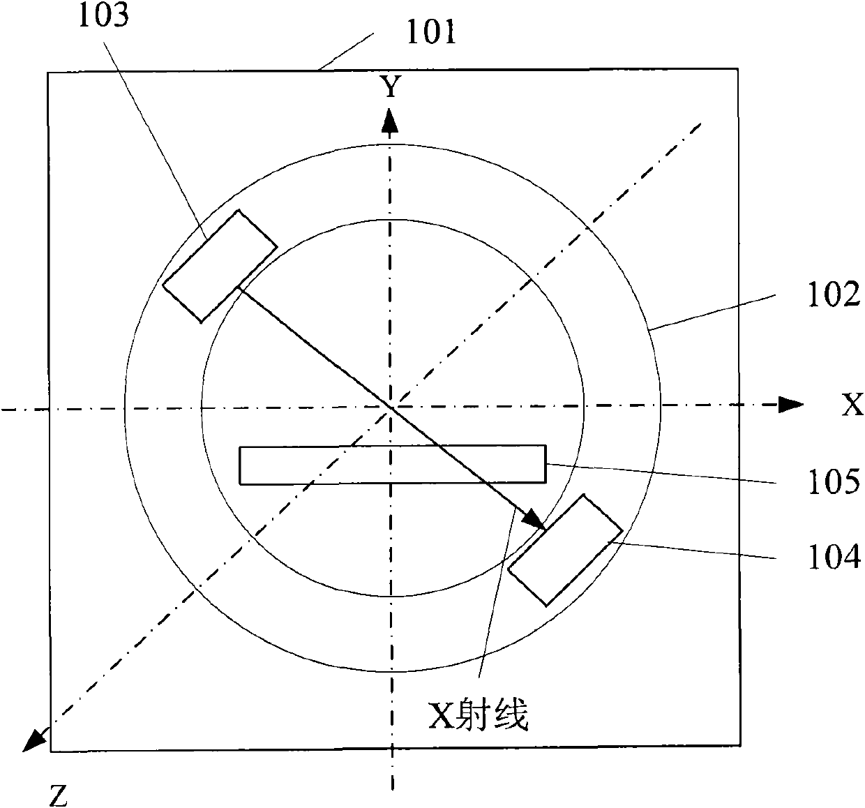
[0028] In order to clearly illustrate this step, firstly, the principle of CT image reconstruction is briefly introduced.

[0029] When the tube and the detector are located at each of the N projection angles, the M channels of the detector receive X-ray signals at the same time. ...


PUM


Abstract

The present invention discloses a method for artifact detection. The method is implemented in such a way that: N groups of projection data corresponding to N projection angles one by one are obtained according to a reconstructed image, wherein each group of projection data includes M projection data corresponding to M channels one by one and N and M are positive integers which are both greater than 1; and calculated are differences between each projection data of the group corresponding to each projection angle and projection data of the group in the same channel corresponding to a previous projection angle or a next projection angle. If the obtained differences are greater than the preset threshold lower limit value and less than the threshold upper limit value, then no artifact exists in the reconstructed image. If any difference of the obtained differences is equal to or greater than the preset threshold upper limit value or equal to or less than the preset threshold lower limit value, then artifact exists in the reconstructed image. Simultaneously, the invention discloses a device for artifact detection. Adopting the method and the device of the invention enables to enhance artifact detection speed and precision.

Description

technical field [0001] The invention relates to computerized tomography (CT, Computed Tomography) technology, in particular to an artifact detection method and device. Background technique [0002] With the progress of medical level, CT scanner has been widely used, figure 1 It is a structural schematic diagram of an existing CT scanner, such as figure 1 As shown, the CT scanner includes: a support 101 , a rotating frame 102 , a tube 103 , a detector 104 and an examination table 105 . Wherein, the rotating frame 102 is generally a ring structure, installed on the bracket 101, the rotating frame 102 is located in the plane determined by the horizontal axis X and the vertical axis Y, and can rotate around the Z axis of the rotating frame 102; A ball tube 103 is installed on the rotating frame 102 for emitting X-rays in a direction perpendicular to the Z axis; a detector 104 is installed on the rotating frame 102 at a position opposite to the ball tube, figure 2 It is a sch...

Claims


Application Information

Patent Timeline
IPC IPC(8): A61B6/03
Inventor 邵军明
Owner SIEMENS SHANGHAI MEDICAL EQUIP LTD
Learn More