A method and apparatus for real-time detection of infrared image abnormality of electric equipment in substation

A power equipment, real-time detection technology, applied in the detection field, can solve problems such as single task, difficult to extract image features of heating areas, large temperature changes, etc., achieve high detection accuracy and speed, real-time automatic detection of abnormalities and faulty equipment Effect

Inactive Publication Date: 2018-12-28
GUIYANG BUREAU OF CHINA SOUTHERN POWER GRID CO LTD EHV TRANSMISSION CO +1
View PDF4 Cites 38 Cited by
  • Summary
  • Abstract
  • Description
  • Claims
  • Application Information

AI Technical Summary

Problems solved by technology

Infrared thermal imager detection has the advantages of non-contact and non-stop power detection of electrical equipment, and is widely used in various power units. With the application and popularization of intelligent equipment such as substation intelligent inspection and fixed-point monitoring, infrared image data continues to increase, and massive inspections Infrared image data is retrieved and analyzed manually, which will be time-consuming and labor-intensive and inefficient
The method of scanning infrared image pixels to find the highest temperature point has defects such as large temperature changes, difficult adjustment of temperature thresholds, large amount of stored data, and inability to sensitively monitor and identify faulty equipment; traditional image processing feature analysis algorithms such as SIFT, SURF, ORB, HOG, etc. are difficult to extract and identify the image features of irregularly shaped heating areas in infrared images
[0003] In the past, infrared detection methods often required manual setting of infrared temperature thresholds or manual observation to judge abnormal fever, which was time-consuming and laborious, and could not be continuously monitored.
The method of using traditional image processing technology to identify abnormal heating of power equipment is often a single task, and the accuracy of identification and practicability are also a big problem

Method used


Image

  • A method and apparatus for real-time detection of infrared image abnormality of electric equipment in substation
  • A method and apparatus for real-time detection of infrared image abnormality of electric equipment in substation
  • A method and apparatus for real-time detection of infrared image abnormality of electric equipment in substation

Examples


Embodiment Construction

[0042] Below, in conjunction with accompanying drawing and specific embodiment, the present invention is described further:

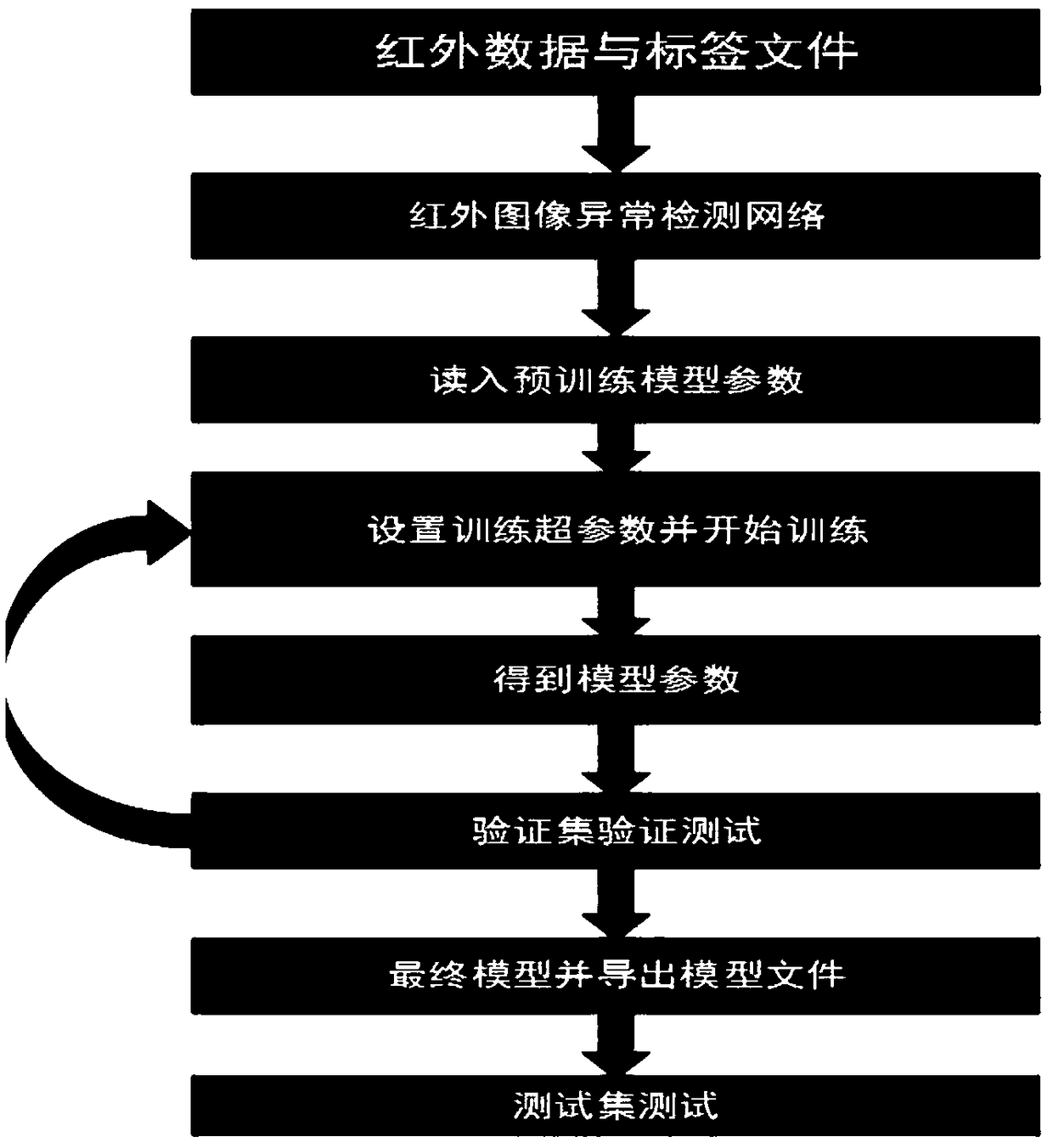
[0043] refer to figure 1 As mentioned above, the real-time detection method for infrared image abnormality of substation power equipment provided by this embodiment specifically includes:

[0044]S1. Collect 1,000 images of abnormal infrared heating of electric equipment, remove abnormal samples, and obtain 863 images I of abnormal infrared heating of electric equipment, which are divided into 20 categories in order to solve the detection tasks of locating abnormalities and classifying faulty equipment. For the location of abnormal fever, in order to solve the detection problem of different shapes and sizes of abnormal areas in infrared images of power equipment, according to the area and shape of red hot areas in infrared images, it is considered to be divided into 7 categories, of which the seventh category is observation Class, and finally will judg...


PUM


Abstract

A method and apparatus for detecting infrared image abnormality of electric power equipment in substation The invention adopts the latest depth learning and the computer vision algorithm to automatically analyze the infrared data and detect the abnormal heat through the collected infrared image or infrared video, which will greatly improve the efficiency and accuracy of the infrared image or infrared video detection. In the substation patrol robot with infrared imager, such intelligent infrared abnormal heating area and fault equipment type detection algorithm based on depth learning are embedded in the upper computer control system such as substation fixed-point monitoring track robot. Real-time infrared image or video detection will further improve the intelligent degree of these intelligent equipment, so as to achieve the real intelligent patrol.

Description

technical field [0001] The detection technology field of the present invention specifically relates to a real-time detection method and device for infrared image abnormality of power equipment in a substation. Background technique [0002] Power equipment is the basic component module of the substation. Timely detection or real-time monitoring of the status of power equipment can efficiently manage these equipment, making the substation more efficient, safe, and reliable. Power outages, thereby greatly reducing the impact of power outages on social, economic, production and life. The abnormal heating of most of the power equipment in the substation is due to poor contact of key parts, loose connection parts, overload, oxidation of old equipment joints, leakage current and other reasons, which cause abnormal heating in some areas of power equipment. Infrared thermal imager detection has the advantages of non-contact and non-stop power detection of electrical equipment, and i...

Claims


Application Information

Patent Timeline
Patent Type & Authority Applications(China)
IPC IPC(8): G06K9/00G06K9/62
CPCG06V20/52G06F18/214G06F18/24
Inventor 叶露孙恒明李浩陈如龙梁廷瞿少君郭天炜张杰冯文华侯谭松王春汤勇罗斌朱俊樊绍胜
Owner GUIYANG BUREAU OF CHINA SOUTHERN POWER GRID CO LTD EHV TRANSMISSION CO
Why Eureka
Try Eureka