
Non-contact detection system of hollow cylindrical part and detection method thereof

A detection system and hollow cylinder technology, which is applied to measurement devices, instruments, optical devices, etc., can solve the problem of low detection accuracy, and achieve the effects of wide applicability, improved efficiency, and good practical value.

Inactive Publication Date: 2010-03-10
SHANGHAI INST OF OPTICS & FINE MECHANICS CHINESE ACAD OF SCI
View PDF0 Cites 35 Cited by
  • Summary
  • Abstract
  • Description
  • Claims
  • Application Information

AI Technical Summary

Problems solved by technology

[0003] The purpose of the present invention is to provide a non-contact detection system and detection method for hollow cylindrical parts in view of the general deficiency of low detection accuracy of detection technology at the present stage. The present invention has the characteristics of high precision and fast speed

Method used


Image

  • Non-contact detection system of hollow cylindrical part and detection method thereof
  • Non-contact detection system of hollow cylindrical part and detection method thereof
  • Non-contact detection system of hollow cylindrical part and detection method thereof

Examples


Embodiment Construction

[0044] The present invention will be further described below in conjunction with the accompanying drawings and specific embodiments, but the scope of protection of the present invention will not only be limited to the expression of the following content.

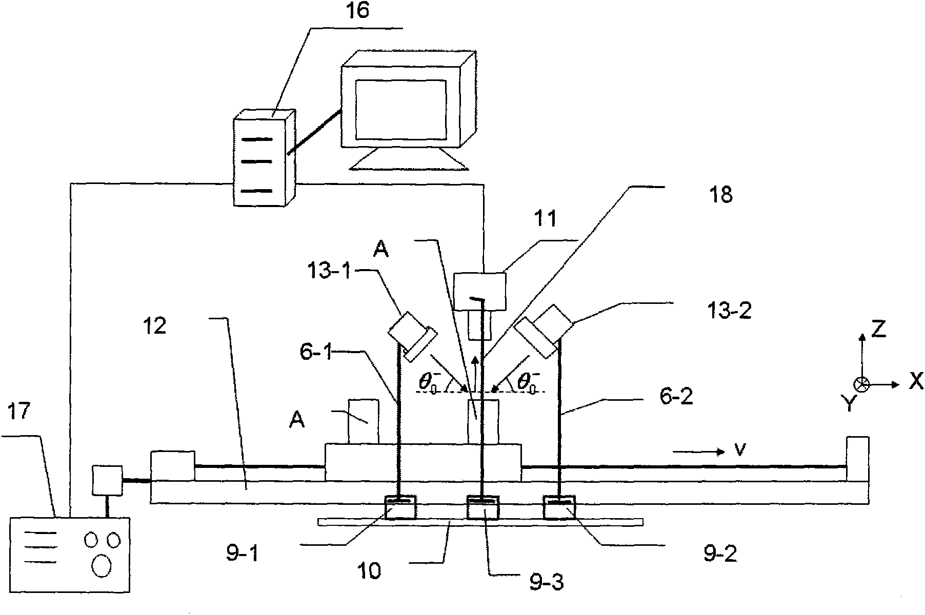
[0045] see first figure 1 , figure 1 It is a schematic diagram of the system structure of the present invention. As can be seen from the figure, the composition of the non-contact detection system of the hollow cylindrical part of the present invention includes:

[0046] Transmission part: it is composed of a controller 17 and an electronically controlled translation platform 12. The electronically controlled translation platform 12 is used to place the hollow cylindrical part to be measured, which is hereinafter referred to as the part A to be tested. The described controller 17 and the described The output terminal of the computer 16 is connected, and the controller 1) drives the motion of the electronically controlled t...


PUM


Abstract

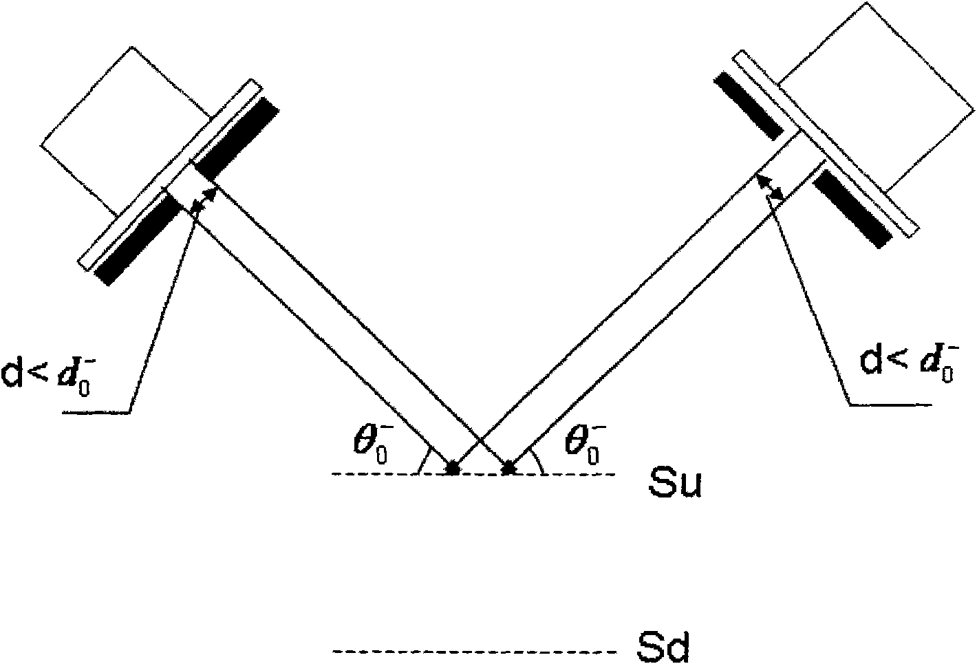
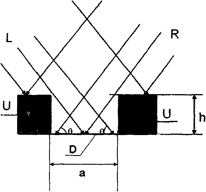
The invention provides a non-contact detection system of a hollow cylindrical part and a detection method thereof. The detection system comprises: an illumination part, a transmission part and a datareceiving processing part, wherein the illumination part comprises a dual parallel light source and a slide way with a bracket and a base; the transmission part comprises a controller and an electriccontrol translational platform; and the data receiving processing part comprises a linear array CCD and a computer with a bracket and a base. One side of the electric control translational platform isprovided with the slide way; the parallel light source and the CCD are respectively arranged on the slide way by the bases thereof; the dual light source is symmetrically positioned relative to the CCD in x direction, and slantwise irradiated on the surface of a part A to be tested from the left upper direction and the right upper direction with angle Theta0<->; the width of the slit of the lightsource is adjusted according to the width upper limit d0<->; the CCD receives the reflected light of the surface of the part from the upper direction; and the data is transmitted to the computer to be processed. The detection method comprises the steps of: harmoniously controlling the translational platform and the CCD by the computer to equidistantly distantly acquire the data; preprocessing theacquired line image and conducting edge extracting; and fitting the circle center position and the circle radius of the outer circle with the circle center position and the circle radius of the innercircle, thus calculating the concentricity of the outer circle and the inner circle.

Description

technical field [0001] The invention relates to automatic detection and visual non-contact detection, in particular to a non-contact detection system and detection method for hollow cylindrical parts. Background technique [0002] Since the 1980s, machine vision has become a global research hotspot. At that time, visual inspection systems have been widely used in American manufacturing, mainly in various automated inspection fields. In recent years, with the great progress of industrial technology in new materials, new processes, new equipment, etc., the technology has been vigorously developed, new concepts and new theories are constantly emerging, and higher requirements are put forward for product testing technology. The traditional contact detection method is slow and easy to cause damage to the parts, which will reduce the measurement accuracy. The measurement technology based on computer vision has the advantages of high speed, good real-time performance, non-contact,...

Claims


Application Information

Patent Timeline
IPC IPC(8): G01B11/27G01B11/08
Inventor 费菲何红
Owner SHANGHAI INST OF OPTICS & FINE MECHANICS CHINESE ACAD OF SCI
Learn More