Automatic advancing and regressing transmission device of movable type doffing machine yarn pulling disc component

A doffer and mobile technology, which is applied to the field of the automatic in-out transmission device for the draw-off disc components of the mobile doffer, can solve the problems of not being fully automatic, uneconomical, and unable to be controlled by a program, so as to improve production efficiency and improve production efficiency. Economic benefits, accurate yarn drawing action, and easy program control

Inactive Publication Date: 2012-11-21
JINGWEI TEXTILE MASCH CO LTD
View PDF5 Cites 0 Cited by
  • Summary
  • Abstract
  • Description
  • Claims
  • Application Information

AI Technical Summary

Problems solved by technology

This type of device has various types. It was originally a hand-push type, and later a motor was added to drive the wheels. However, the degree of automation is very low, and manual operation is still required. The labor intensity is high, and the yarn-drawing disc also damages the cotton yarn; the yarn-drawing disc parts enter and exit the working position It needs to be operated by hand, cannot be controlled by a program, and cannot be fully automatic. Compared with the collective automatic doffing device, there is still a big gap, and it needs to be improved and perfected urgently
After the introduction of foreign spinning frames with collective doffing devices in recent years, domestic research and development of this type of advanced device has achieved results, but this type of device is suitable for long spinning frames with more than 800 spindles. The cost performance of the collective doffing device on the machine is too low and uneconomical, and the machine arrangement space in the workshop is not allowed

Method used


Image

  • Automatic advancing and regressing transmission device of movable type doffing machine yarn pulling disc component
  • Automatic advancing and regressing transmission device of movable type doffing machine yarn pulling disc component

Examples


Embodiment Construction

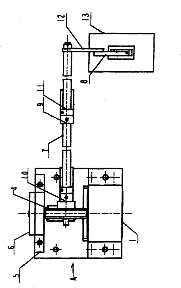
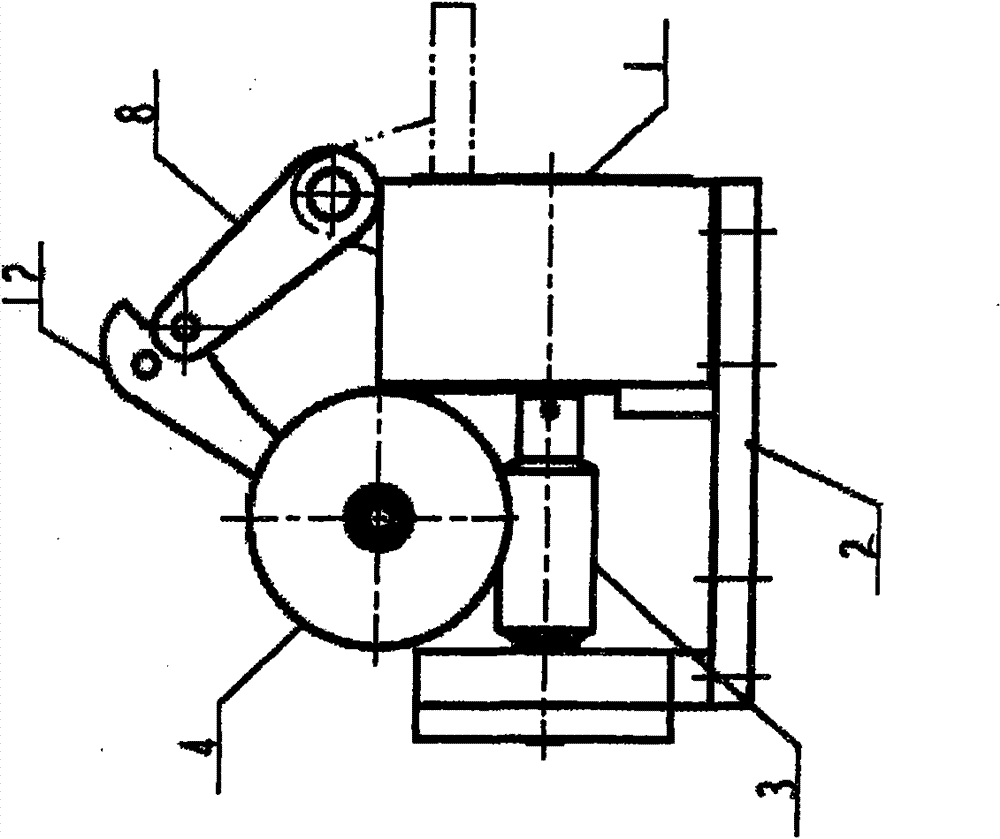
[0010] The micro-motor 1 controlled by the program can rotate forward and reversely, and the base plate 13 of the terminal part spinning disc component can be advanced and retreated through the transmission system, and automatically enters and exits the working position. The motor 1 drives the worm 3, the worm 3 drives the worm gear 4, and the worm gear 4 is fastened on the left end of the transmission long shaft 7, and the torque is transmitted to the connecting rod 12 fixedly mounted on the right end of the transmission long shaft 7 through the transmission long shaft 7, so that the connecting rod 12 is in the Synchronous rotation on the transmission long shaft 7 can make the crank 8 whose upper end is hinged with the connecting rod 12 follow up, and the other end of the crank 8 pushes or pulls the bottom plate 13 of the yarn pulling disc component to move on the moving guide rail below it, so that the yarn pulling The main parts such as the yarn-drawing disk and the pre-loos...


PUM


Abstract

The invention relates to an automatic advancing and regressing transmission device of a movable type doffing machine yarn pulling disc component. A micro motor (1) and a bearing seat (5) are arranged on a mounting seat (2), a bearing cover (6) is arranged on the bearing seat (5), the micro motor (1) is connected with a worm (3), the worm (3) is meshed with a worm wheel (4), the worm wheel (4) is arranged on the left end of a transmission long shaft (7), the long shaft (7) is arranged in a right oil-containing bearing seat (9) and a left oil-containing bearing seat (10), a locating ring (11) is arranged on the long shaft (7), a connecting rod (12) is arranged at the right end of the transmission long shaft (7), the upper end of a crank (8) is hinged with the connecting rod (12), and the lower end of the crank (8) is connected with a yarn pulling disc component mounting base plate (13). When the invention is applied to a ring spinning movable type doffing machine, the operation process of the doffing machine can be more accurate and reliable, the automatic control is realized, the doffing labour intensity can be reduced, and the application range of the movable type doffing machine can be expanded.

Description

technical field [0001] The invention belongs to a component for doffing of a ring spinning machine, in particular to a transmission device for automatically entering and exiting a drawing disc component of a mobile doffer. Background technique [0002] The ring spinning frame is the main process machine used in the largest number in textile mills. Cotton goes through the processes of opening, carding, drawing, combing, roving, etc., and finally enters the spinning frame to be spun into spun yarns that meet the requirements. The spun yarn is wound on the bobbins, and the full bobbins are pulled out one by one from the spindles, transported out, and then inserted into the empty bobbins one by one, which is a repeated, tedious and laborious doffing process. Because the scale of a textile factory is often tens of thousands or hundreds of thousands of spindles, its labor intensity, time-consuming and labor-intensive degree can be imagined. Textile enterprises in our country have...

Claims


Application Information

Patent Timeline
Patent Type & Authority Patents(China)
IPC IPC(8): D01H9/02
Inventor 赵镇尧
Owner JINGWEI TEXTILE MASCH CO LTD
Why Eureka
Try Eureka