Two-stage compression refrigerating system

A two-stage compression and refrigeration system technology, applied in refrigerators, compressors, refrigeration components, etc., can solve the problems of uneconomical volume ratio of high and low pressure cylinders, inflexible energy regulation of refrigeration systems, and large temperature fluctuations in cold storage, etc., to achieve improved The effect of high efficiency, flexible adjustment and small temperature fluctuation

Inactive Publication Date: 2011-04-20
TIANJIN TIANXING ELECTRONICS +1
View PDF10 Cites 20 Cited by
  • Summary
  • Abstract
  • Description
  • Claims
  • Application Information

AI Technical Summary

Problems solved by technology

The compression volume ratio of the high-pressure refrigeration compressor and the low-pressure refrigeration compressor in the prior art is generally fixed at 1:3 or 1:2, but since the condensation pressure of the refrigeration system changes with the ambient temperature, the intermediate pressure of the system and the refrigeration The cylinder volume ratio of the compressor and the low-pressure stage refrigeration compressor will also change constantly, which is uneconomical for the designed high-low pressure cylinder volume ratio
In addition, because the existing two-stage compression refrigeration system adopts the fixed frequency method, the energy regulation of the refrigeration system is not flexible, and the system can only rely on the start and stop of the system for energy regulation, resulting in large temperature fluctuations in the cold storage

Method used


Image

  • Two-stage compression refrigerating system
  • Two-stage compression refrigerating system
  • Two-stage compression refrigerating system

Examples


Embodiment 1

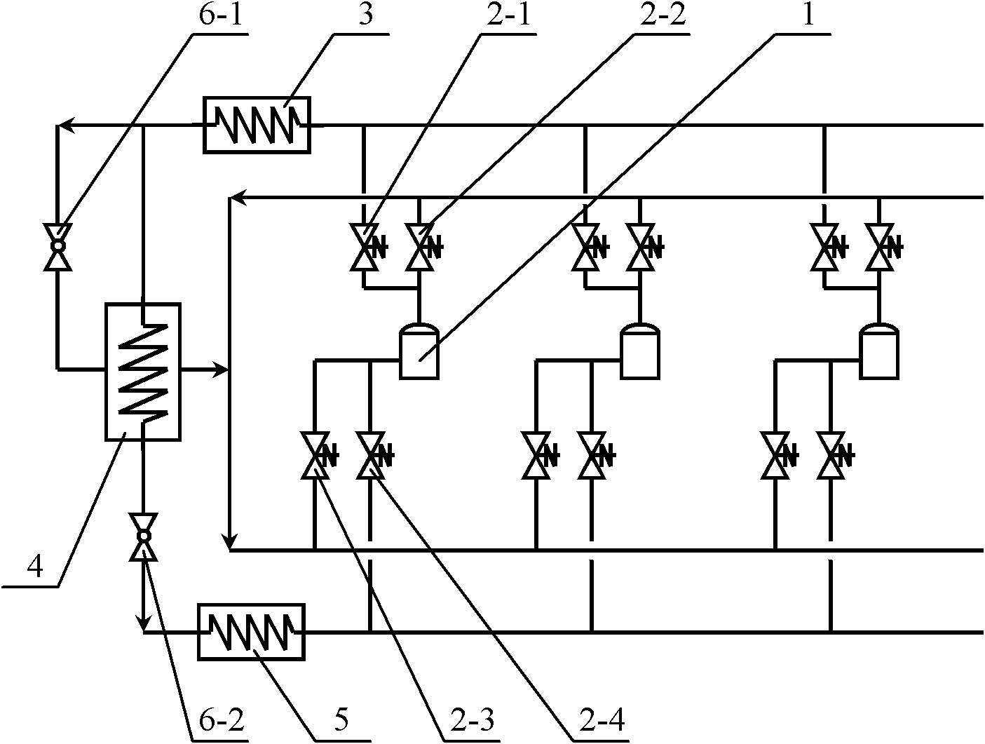
[0019] figure 1 It is a schematic diagram of a two-stage compression refrigeration system with one-stage throttling and incomplete cooling in the middle of the present invention, including multiple refrigeration compressors 1, condenser 3, evaporator 5, and intercooler 4. The intercooler is a shell-and-tube heat exchange or plate heat exchanger. The discharge end of each refrigeration compressor 1 is respectively connected with the first electromagnetic valve 2-1 and the second electromagnetic valve 2-2, and the suction end of each refrigeration compressor is respectively connected with the third electromagnetic valve 2-3 and the second electromagnetic valve 2-3. Four solenoid valves 2-4, the first solenoid valve 2-1 connected to each refrigeration compressor is connected in parallel to the inlet of the condenser 3, and the second solenoid valve 2-2 connected to each refrigeration compressor is connected in parallel to the middle The shell side outlet of the cooler 4 is conne...

Embodiment 2

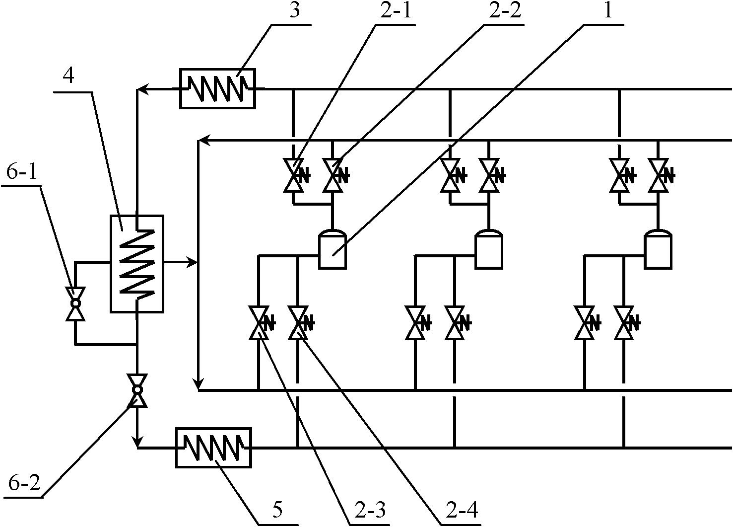
[0029] figure 2It is a schematic diagram of another two-stage compression refrigeration system with one-stage throttling and incomplete cooling in the middle of the present invention. The connection mode of the first throttling valve is different, and the other structures are exactly the same as in Embodiment 1.

[0030] It includes multiple refrigeration compressors 1, condensers 3, evaporators 5, and intercoolers 4, and the intercoolers are shell-and-tube heat exchangers or plate heat exchangers. The discharge end of each refrigeration compressor 1 is respectively connected with the first electromagnetic valve 2-1 and the second electromagnetic valve 2-2, and the suction end of each refrigeration compressor is respectively connected with the third electromagnetic valve 2-3 and the second electromagnetic valve 2-3. Four solenoid valves 2-4, the first solenoid valve 2-1 connected to each refrigeration compressor is connected in parallel to the inlet of the condenser 3, and th...

Embodiment 3

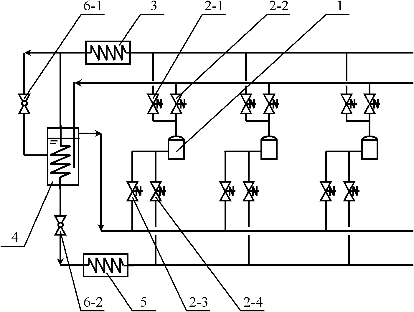
[0039] image 3 It is a schematic diagram of a two-stage refrigeration compression system with one-stage throttling and complete cooling in the middle, including multiple refrigeration compressors 1, condenser 3, evaporator 5, and intercooler 4. The intercooler is a shell-and-tube type with a liquid surface Heat Exchanger. The discharge end of each refrigeration compressor is respectively connected with the first electromagnetic valve 2-1 and the second electromagnetic valve 2-2, and the suction end of each refrigeration compressor is respectively connected with the third electromagnetic valve 2-3 and the fourth electromagnetic valve 2-3. Solenoid valve 2-4, the first solenoid valve 2-1 connected to each refrigeration compressor is connected in parallel to the inlet of the condenser 3, and the second solenoid valve 2-2 connected to each refrigeration compressor is connected in parallel to the intermediate cooling The shell side interface below the liquid surface of the device...


PUM


Abstract

The invention discloses a two-stage compression refrigerating system. The two-stage compression refrigerating system is easy for energy regulation and can realize switch between a high-pressure refrigerating compressor and a low-pressure refrigerating compressor so as to improve the efficiency of the refrigerating system. The air exhaust end of each refrigerating compressor is respectively connected with a first electromagnetic valve and a second electromagnetic valve, and the air suction end of each refrigerating compressor is respectively connected with a third electromagnetic valve and a fourth electromagnetic valve. After the parallel connection, all the first electromagnetic valves connected on the refrigerating compressors are connected with an inlet of a condenser. After the parallel connection, all the second electromagnetic valves connected on the refrigerating compressors are connected with an outlet at the shell side of an intercooler. After the parallel connection, all the third electromagnetic valves connected on the refrigerating compressors are connected with the outlet at the shell side of the intercooler. After the parallel connection, all the fourth electromagnetic valves connected on the refrigerating compressors are connected with an outlet of an evaporimeter. Through the opening or closing of the electromagnetic valves connected with the refrigerating compressors, the switch between the high-pressure stage and the low-pressure stage can be realized.

Description

technical field [0001] The present invention relates to a refrigeration cycle system, more specifically to a multi-head two-stage compression refrigeration cycle, which is used to improve the efficiency of the two-stage compression refrigeration cycle and to regulate the energy of the refrigeration capacity of the refrigeration system. Background technique [0002] The two-stage compression refrigeration system is to compress the low-temperature and low-pressure refrigerant vapor from the evaporator to an appropriate intermediate pressure with the low-pressure refrigeration compressor, then enter the high-pressure refrigeration compressor and compress it to the condensation pressure again, and discharge it into the condenser. The system is suitable for refrigeration systems with large compression ratio. The compression volume ratio of the high-pressure refrigeration compressor and the low-pressure refrigeration compressor in the prior art is generally fixed at 1:3 or 1:2, bu...

Claims


Application Information

Patent Timeline
Patent Type & Authority Applications(China)
IPC IPC(8): F25B1/00F25B41/04F25B41/06
Inventor 杨永安李砚明董小勇严雷叶庆银毛力陆佩强
Owner TIANJIN TIANXING ELECTRONICS
Why Eureka
Try Eureka