High-precision distributed pulse signal time difference of arrival detection system

A pulse signal and detection system technology, which is applied in the field of civil aviation, can solve the problems of difficult wiring and cable layout, and the distance between stations cannot be too large, so as to reduce the target positioning error and improve the overall performance.

Active Publication Date: 2011-04-20
THE SECOND RES INST OF CIVIL AVIATION ADMINISTRATION OF CHINA
4 Cites 58 Cited by

AI-Extracted Technical Summary

Problems solved by technology

[0018] It is difficult to lay out wired cables at airports that have already been put into use;
[0019] The use of wired cables for clock comparison requires th...

Abstract

The invention discloses a high-precision distributed pulse signal time difference of arrival (TDOA) detection system. The system consists of a time of arrival (TOA) detection module in a multi-point positioning distant station and a target TOA calculation module in a multi-point positioning central processing station; and the system synchronously corrects time delay errors of a system time synchronization signal processing channel and a target signal processing channel by adopting a method combining global position system (GPS) common-view technology and reference responder synchronization error correction, and corrects TOA measurement errors and TDOA measurement errors in real time by using multiple filter and tracking algorithms. The system makes up the defects of single mode, and realizes high-precision distributed pulse signal TDOA detection so as to reduce the target positioning errors and improve the integral performance of a multi-point positioning system.

Application Domain

Technology Topic

Time of arrivalMultilateration +8

Image

  • High-precision distributed pulse signal time difference of arrival detection system
  • High-precision distributed pulse signal time difference of arrival detection system
  • High-precision distributed pulse signal time difference of arrival detection system

Examples

  • Experimental program(1)

Example Embodiment

[0057] All features disclosed in this specification, or all disclosed steps in a method or process, may be combined in any way except mutually exclusive features and/or steps.
[0058] Any feature disclosed in this specification (including any accompanying claims, abstract and drawings), unless expressly stated otherwise, may be replaced by other equivalent or alternative features serving a similar purpose. That is, unless expressly stated otherwise, each feature is but one example of a series of equivalent or similar features.
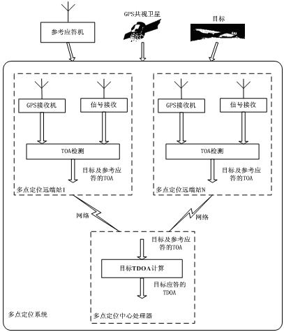
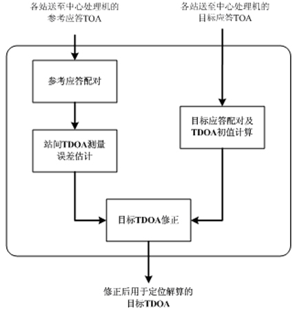
[0059] Reference Answer Pairing and Target Answer Pairing:
[0060] The target TDOA calculation module receives the data sent by each remote station, and preprocesses the data. The target symbol and TOA are extracted. For the target TDOA calculation module, the reference response is only a special target. Other processing flow and goals are the same.
[0061] Assume that the time difference TDOA of a certain target reaching two remote receivers (No. 1 and No. 2) is , the distances of the target from the two remote receivers are and , the distance between the two remote stations is. The maximum time difference between the target and the same signal reaching each remote station is , the maximum distance between two remote stations is.
[0062] According to the difference between the two sides of the triangle is less than the third side, we can get: , due to the propagation speed of the signal The same, it can be known that the time difference between the target arrival at the two stations. The same can be obtained.
[0063] Knowing the ready location information of each remote station, the central processing unit can calculate the distance between all remote receivers, and select the distance between them. , so that it can be obtained upper limit of . Identify the same target according to the symbols of the pulse signal, and for the same target, the TDOA value of the target cannot exceed upper limit of . In this way, the problem of pulse signal TOA pairing is simply completed.
[0064] Inter-station TDOA error estimation:
[0065] like Figure 4 shown. The geometric position of the reference transponder is known and fixed, the theoretical time difference of the reference reply signal transmitted to each station can be calculated, and then the time offset between the stations can be obtained according to the TDOA between the actually measured reference reply signal arriving at each station The time offset is the synchronization error caused by different system delays.
[0066] The location of the reference transponder and the receiving station has been determined, then the reference transponder signal is sent to any two stations and The theoretical time difference is
[0067]
[0068] in, is the speed of signal propagation, For reference answering machine to site the distance. Actual measurement to the reference response signal to any two sites and The time difference is
[0069]
[0070] Therefore, the synchronization error between stations can be estimated by using the theoretical TDOA value and the measured TDOA value.
[0071] .
[0072]
[0073] Target TDOA Correction:
[0074] For the target signal after TDOA pairing, the target TDOA correction is performed on the basis of the TDOA error estimation of the site.
[0075] For the received target signal, there are
[0076]
[0077] in, is the theoretical value of the time difference between the target signal and the station. measured Value contains site sync error , Estimated from the reference response TDOA error. from the measured The synchronization error is eliminated from the value, and the corrected target TDOA is obtained as
[0078]
[0079] Thereby, the correction of the synchronization error between the sites is realized.
[0080]
[0081] The present invention is not limited to the foregoing specific embodiments. The present invention extends to any new features or any new combination disclosed in this specification, as well as any new method or process steps or any new combination disclosed.

PUM

no PUM

Description & Claims & Application Information

We can also present the details of the Description, Claims and Application information to help users get a comprehensive understanding of the technical details of the patent, such as background art, summary of invention, brief description of drawings, description of embodiments, and other original content. On the other hand, users can also determine the specific scope of protection of the technology through the list of claims; as well as understand the changes in the life cycle of the technology with the presentation of the patent timeline. Login to view more.

Similar technology patents

Software defined network link fault recovery method based on in-band control

ActiveCN107302496AImprove overall performanceData switching networksHigh level techniquesLink Layer Discovery ProtocolControl flow
Owner:CHONGQING UNIV OF POSTS & TELECOMM

Antistatic finishing process of chemical fiber fabric

InactiveCN103993473AImprove comfort performanceImprove overall performanceSynthetic fibresDyeing processDyeingPolymer chemistry
Owner:TAICANG MENGFAN CHEM FIBER

Classification and recommendation of technical efficacy words

Why Eureka
Try Eureka