Time focusing and time collimating method and device of ultra-short electron beam bunch

An electron beam, time technology, applied in the field of electron optics, can solve the problem of not providing a time compressor and a collimator, etc.

Inactive Publication Date: 2011-04-20
SHENZHEN UNIV
View PDF1 Cites 6 Cited by
  • Summary
  • Abstract
  • Description
  • Claims
  • Application Information

AI Technical Summary

Problems solved by technology

But there is no time compressor and collimator that can achieve a time resolution of less than 150fs

Method used


Image

  • Time focusing and time collimating method and device of ultra-short electron beam bunch
  • Time focusing and time collimating method and device of ultra-short electron beam bunch
  • Time focusing and time collimating method and device of ultra-short electron beam bunch

Examples


Embodiment 1

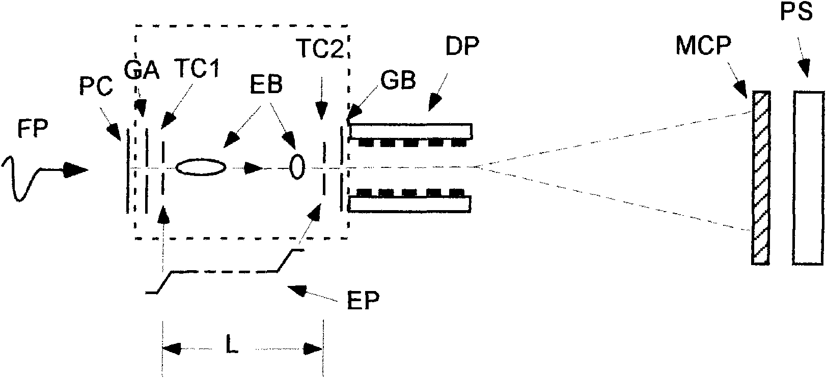
[0031] Example 1, such as figure 1 As shown, the present embodiment is a device for realizing ultra-short electron beam time focusing and time collimation in the range of nanoseconds to picoseconds. The ultrashort electron beam time focusing and time collimation device includes A time focuser, a time collimator, and a ramp electric pulse EP generator are arranged in sequence along the advancing direction of the electron beam EB in a vacuum cavity (the part inside the dotted line frame in the figure), and the time focuser and the time collimator are separated by A design distance L.

[0032] The time focuser includes the time focuser ground electrode GA and the time focuser pulse electrode TC1, the distance between the time focuser ground electrode GA and the time focuser pulse electrode TC1 is 5mm, and the time focuser ground electrode GA and the time focuser pulse electrode The electric pulse EP output terminal of the electric pulse EP generator is connected between the elec...


PUM


Abstract

The invention provides a time focusing and time collimating method and device of an ultra-short electron beam bunch. The method is characterized in that in a cavity-shaped structure, front electron beams in the electron beam bunch have low acceleration, and back electron beams in the electron beam bunch have high acceleration; after a specific distance, the back electrons in the electron beam bunch catch up with the front electrons in the electron beam bunch, thereby realizing the time compression; and meantime, the electron beam bunch is decelerated, wherein the deceleration of the front electrons is low, and the deceleration of the back electrons is high, so that the movement speeds of the electrons are equivalent, thereby realizing the time collimation. After uneven acceleration, the time width of the electron beam bunch is compressed to 200fs by the invention, and the time compression ratio reaches 3:1.

Description

technical field [0001] The invention belongs to the field of electron optics, in particular to electron beam cluster and particle beam technology. Background technique [0002] With the development of ultrashort laser technology, researchers have obtained laser pulses with a width of several photoperiods; however, the relative backwardness of ultrafast measurement technology (especially in the X-ray band) has seriously hindered the requirement for high time-resolved The progress of research work, including soft X-ray high-order harmonic measurement, femtosecond electron diffraction, synchrotron radiation accelerator technology and ultrafast photobiological phenomena, etc. In recent years, the time resolution of traditional X-ray streak cameras has been increased to about 300fs, as in the paper "Achieving 280fs resolution with a streak camera by reducing the deflection dispersion", these experimental results are realized by increasing the field strength between the cathode a...

Claims


Application Information

Patent Timeline
Patent Type & Authority Applications(China)
IPC IPC(8): H01J23/08
CPCH01J23/08
Inventor 刘进元龙井华
Owner SHENZHEN UNIV
Why Eureka
Try Eureka