Brightness correction method and system for display device

A technology for display device and brightness correction, which is applied to measurement devices, photometry, and components of TV systems, etc., and can solve problems such as high brightness, dark edges and corners of the screen, etc.

Inactive Publication Date: 2011-04-20
GUANGDONG VTRON TECH CO LTD
View PDF6 Cites 33 Cited by
  • Summary
  • Abstract
  • Description
  • Claims
  • Application Information

AI Technical Summary

Problems solved by technology

[0004] The first object of the present invention is to provide a method for correcting the brightness of a display device to solve the technical problem in the prior art that the brightness of the center area of ​​a single projection display unit is greater than that of the edge area, that is, the phenomenon of dark edges and dark corners of the screen

Method used


Image

  • Brightness correction method and system for display device
  • Brightness correction method and system for display device
  • Brightness correction method and system for display device

Examples


Embodiment Construction

[0091] The present invention will be described in further detail below in conjunction with the accompanying drawings and specific embodiments.

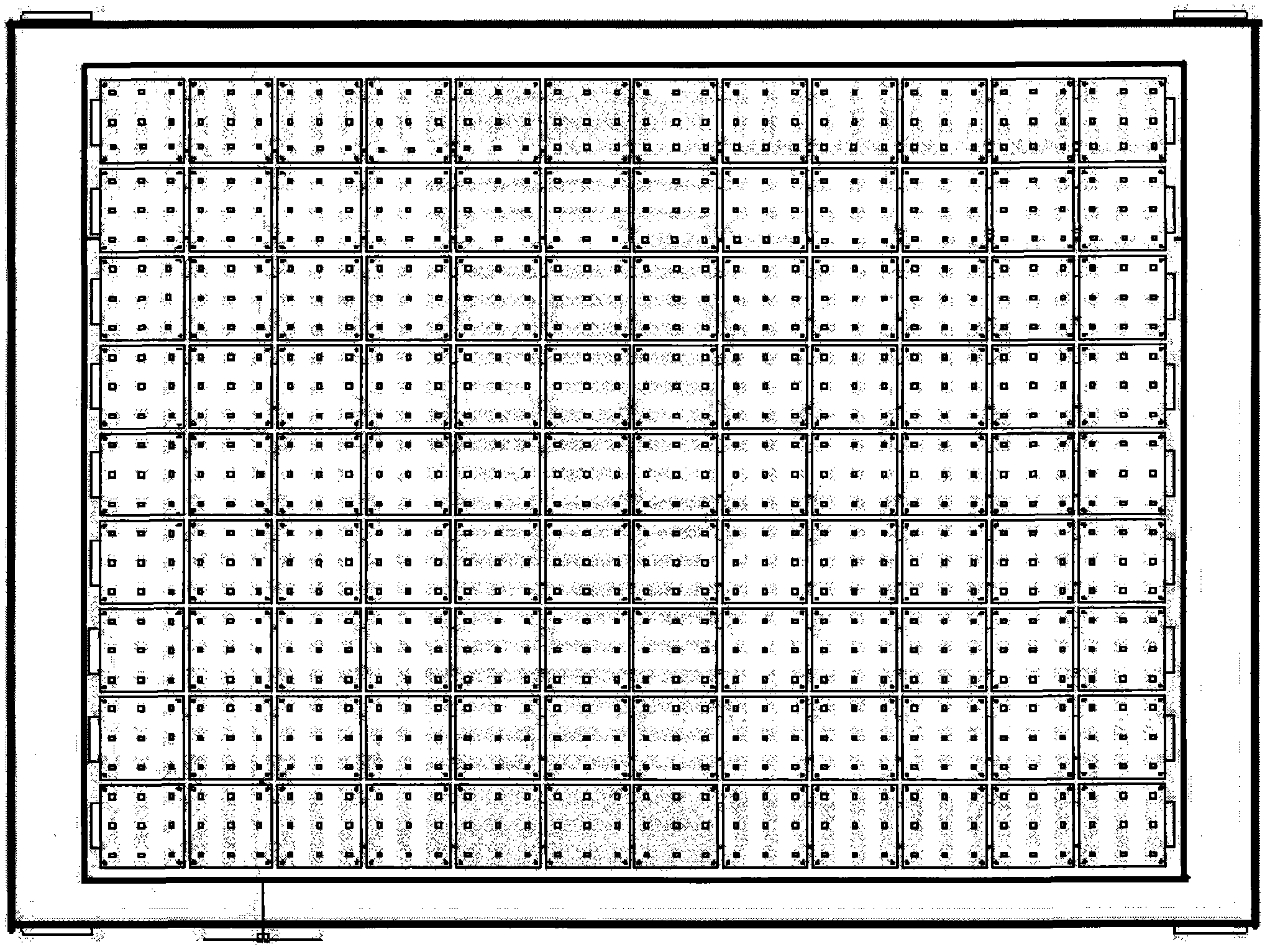
[0092] In order to collect the luminance value of the display in the embodiment of the present invention, a mounting board equipped with a luminance sensor is designed, such as figure 1 shown. There are 9×12 MCUs (that is, central processing units) on the sensor mounting board, and there are 9 sensors on each MCU. The size of the MCU is: 93×93mm, the interval between the MCU and the MCU is 6mm, the interval between each sensor on the MCU is 33mm, and the distance between the sensor and the edge of the MCU is 13.5mm.

[0093] Control the projector core, display red, green, and blue on the projector screen respectively, and after obtaining the brightness of each pixel on the display screen, calculate each color under different colors for red, green, and blue according to the method in the text. The compensation coefficients Gr, Gg, G...


PUM


Abstract

The invention relates to the technical field of display devices, in particular to brightness correction method and system for a display device. In the method, (1) brightness correction is carried out on more than one brightness sensor; (2) in the normal operation of the display device, the brightness values of the brightness sensors after brightness correction are used as the brightness value of pixel points corresponding to the brightness sensors; (3) brightness collecting interpolation is carried out on pixel points without the arrangement of the brightness sensors to obtain the brightness values corresponding to the pixel points; and (4) local brightness compensating factor calculation and brightness compensation are carried out to each pixel point. The brightness correction method and the brightness correction system have the characteristics of clear structure and simple calculation and are easy to realize, and when a single-screen brightness is corrected, the brightness compensation calculation is carried out by taking a small screen as a unit, therefore, the minimum compression of the brightness values of all the pixel points is avoided and the brightness loss is effectively reduced.

Description

technical field [0001] The invention relates to the technical field of display devices, in particular to a brightness correction method and system for a display device. Background technique [0002] Projection splicing systems are widely used in business meetings, advertising, industrial control, traffic monitoring, etc. The demand for large-screen display equipment and technologies in more and more fields is also growing rapidly. However, during the use of splicing systems, often Encountered a difficult problem: how to achieve the brightness and color uniformity of the video wall. Brightness and color uniformity have become an important parameter to measure the quality of a projection video wall system. [0003] The projection splicing wall is composed of a single projection display unit. In the prior art, the brightness of the central area of ​​a single projection display unit is greater than that of the edge area, that is, the phenomenon of dark edges and dark corners of...

Claims


Application Information

Patent Timeline
Patent Type & Authority Applications(China)
IPC IPC(8): H04N5/74H04N9/31G01J1/00G06F3/048
Inventor 彭春山武海丽张海燕
Owner GUANGDONG VTRON TECH CO LTD
Why Eureka
Try Eureka