Method of reducing torsional oscillations in the power train of a wind turbine

A technology for wind turbines and power trains, applied in the control of wind turbines, wind turbines, and combinations of wind turbines, etc., can solve the problems of not always producing satisfactory results, expensive, complicated methods, etc.

Inactive Publication Date: 2011-04-20
阿尔斯通风力有限个人公司
View PDF8 Cites 2 Cited by
  • Summary
  • Abstract
  • Description
  • Claims
  • Application Information

AI Technical Summary

Problems solved by technology

[0008] The prior art methods are complex and therefore expensive
Furthermore, they do not always produce satisfactory results

Method used


Image

  • Method of reducing torsional oscillations in the power train of a wind turbine
  • Method of reducing torsional oscillations in the power train of a wind turbine
  • Method of reducing torsional oscillations in the power train of a wind turbine

Examples


Embodiment Construction

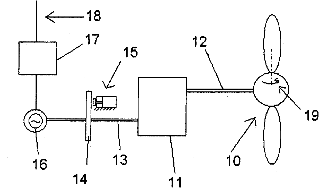
[0043] refer to figure 1 , shows a schematic diagram of a wind turbine. The rotor 10 includes a plurality of blades. The blades are mounted on the rotor shaft (also called: low speed shaft) 12 . The gearbox 11 converts the rotational motion of the rotor shaft into the rotational motion of the high speed shaft 13 . A brake disc 14 is mounted on the high speed shaft. The hydraulic brake is indicated with reference numeral 15 . In this figure, a possible embodiment of a braking system usable in the method according to the invention is shown. In principle, however, any type of brake can be used in the method according to the invention.

[0044] The high speed shaft 13 moves the rotor of the generator 16 . The electrical power produced by the generator is fed into an electrical grid 18 through appropriate electrical components generally indicated by reference numeral 17 . Reference numeral 19 designates the pitch system of the blades, which makes it possible to turn the blad...


PUM


Abstract

The present invention refers to a method of reducing torsional oscillations in the power train of a wind turbine in the event of grid loss. According to the method, after the grid loss, a braking torque is applied to the power train during a period of time and said period of time is determined as a function of the torsional resonance frequency of the power train.

Description

technical field [0001] The invention relates to a method of controlling a wind turbine. More precisely, the invention relates to a method of controlling a wind turbine in the event of a grid loss. Background technique [0002] Modern wind turbines are commonly used to supply electricity into the grid. Wind turbines of this kind generally comprise a rotor with a plurality of blades. A rotor with blades turns under the influence of wind on the blades. The rotation of the rotor shaft directly drives the generator rotor ("direct drive"), or drives the generator rotor through the use of a gearbox. [0003] During normal operation, the rotational speed of a wind turbine is controlled by the magnetic torque acting on the generator and the aerodynamic torque acting on the rotor. Additionally, braking systems are generally foreseen. [0004] Various approaches are known for controlling the aerodynamic moments acting on the rotor of a wind turbine. In a "pitch-regulated" wind tu...

Claims


Application Information

Patent Timeline
Patent Type & Authority Applications(China)
IPC IPC(8): F03D11/02F03D7/02
CPCY02E10/723F05B2270/1011Y02E10/725F05B2260/902Y02E10/722F05B2260/96Y02E10/72F03D7/0248F03D11/02F05B2270/103F03D9/25F03D15/00F03D15/10
Inventor D·卡斯特利马丁内斯C·卡萨诺瓦斯贝尔梅霍
Owner 阿尔斯通风力有限个人公司
Why Eureka
Try Eureka