Electric pressure steamer

An electric steamer and pressure technology, applied in pressure cookers, steam cooking utensils, etc., can solve the problems of slow steam speed, high water consumption, steam leakage, etc., and achieve the effect of increased cooking speed, less water consumption and uniform heating

Active Publication Date: 2011-04-27
ZHEJIANG SUPOR ELECTRICAL APPLIANCES MFG CO LTD
View PDF8 Cites 15 Cited by
  • Summary
  • Abstract
  • Description
  • Claims
  • Application Information

AI Technical Summary

Problems solved by technology

The temperature of the steam produced by the electric steamer with this structure is not high, it can only reach 100°C at most, the efficiency is slow, and the steam leaks out, which consumes a lot of water
[0004] Some commercially available electric pressure cookers have the function of steaming, but due to the slow speed of steam generation, and the small volume of electric pressure cookers, the amount of steamed food is small, which cannot meet the needs of daily life
[0005] Chinese invention patent CN1038930 (announcement date is January 24, 1990) discloses a steam heat pot. The pot is divided into an inner pot and an inner pot. The space is completely heated by steam and gradually transmitted to the entire inner pot. The steam heat energy pot has an adjustable pressure control valve, which can generate a certain pressure. However, when the steam heat energy pot is in use, there is no steam on the upper surface of the food in the inner pot. , and can not achieve all-round heating; and the inner pot cannot be replaced, and the function is relatively single

Method used


Image

  • Electric pressure steamer
  • Electric pressure steamer
  • Electric pressure steamer

Examples


Embodiment 1

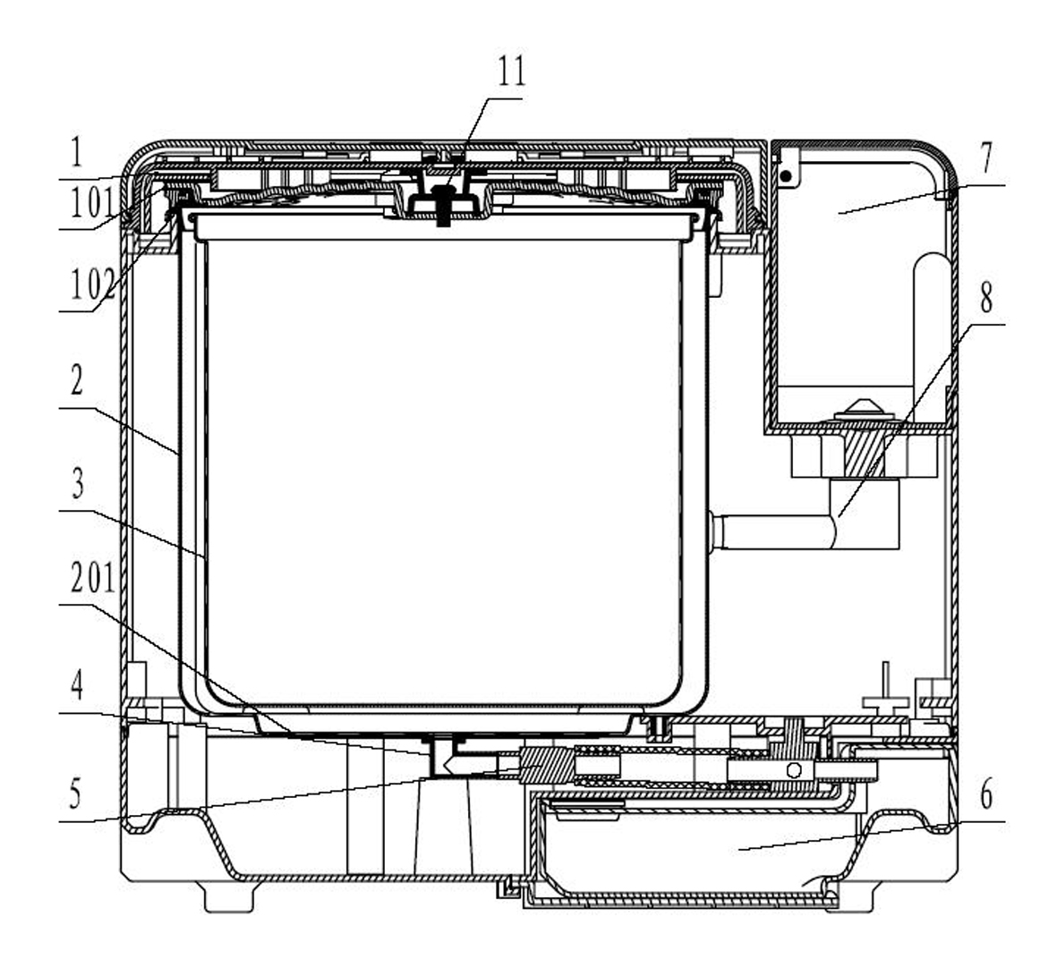
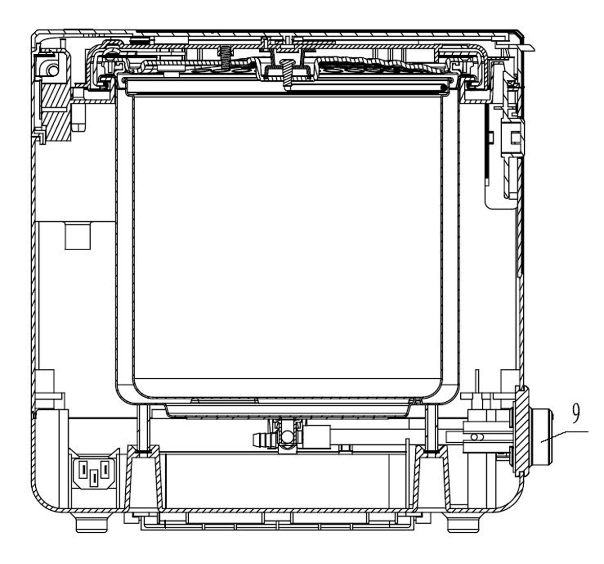
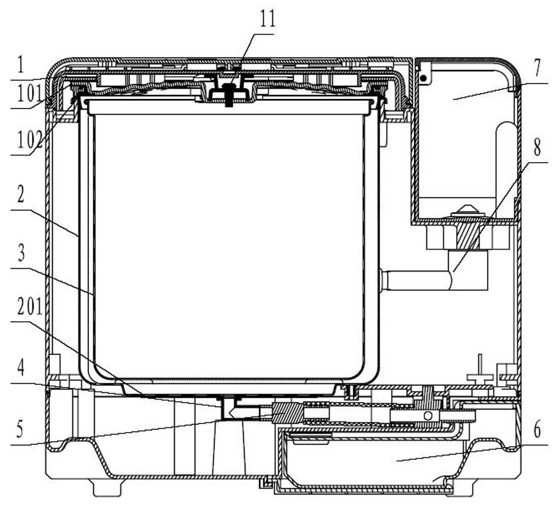
[0030] The pressure electric steamer of present embodiment, see figure 1 with figure 2 As shown, it includes an outer pot 2 inside the pot body, an inner pot 3 placed inside the outer pot for cooking food, a pot lid 101 fastened on the outer pot, a water tank 7 for containing water sources, and an electric heating element at the bottom of the outer pot 201 and the control circuit for controlling the electric heating device, different from the traditional pressure electric steamer, the present invention is provided with a sealing ring between the pot cover 101 and the outer pot 2, the sealing ring is as figure 1 The shown card is placed in the groove on the edge of the pot cover 101, the outer edge of the section of the sealing ring is attached to the inner surface of the outer pot mouth, and the upper cover 1, the pot cover 101 and the outer pot are sealed and locked with each other through the lock buckle and the sealing ring. The distance between the pressure chamber, the ...

Embodiment 2

[0039] The difference from Embodiment 1 is that there is a cavity inside the drainage box body 6, and the cavity is filled with a condensing agent, which can be various commercially available reagents for liquid condensation.


PUM


Abstract

The invention discloses an electric pressure steamer, which comprises an outer steamer of a steamer body, an inner steamer or a steaming layer which is arranged inside the outer steamer and is used for steaming foods, a steamer cover covering the outer steamer, an electrical heating element at the bottom of the outer steamer, and a control circuit for controlling an electrical heating device. The electric pressure steamer is characterized in that: a sealing element for providing a pressure seal is arranged between the steamer cover and the outer steamer; the steamer cover and the outer steamer are sealed to form a pressure cavity; the inner steamer or the streaming layer is supported to be separated from the surface of the electrical heating element; a water and air outlet is formed at the bottom of the outer steamer and is communicated with a water outlet box at the bottom of the steamer body through a water outlet channel; and a water and air valve is arranged between the water outlet channel and the water outlet box. Compared with the electric steamer in the prior art, the electric pressure steamer has the advantages that: the outer steamer and the steamer cover are sealed, steam does not overflow, the energy and electricity are saved, the steaming speed is improved under the pressure, and the pressure in the steamer is rapidly reduced.

Description

[0001] technical field [0002] The invention belongs to the technical field of electric steamers, in particular to a pressure electric steamer with improved steam temperature and cooking efficiency. Background technique [0003] An electric steamer is a household kitchen appliance that uses the principle of electric steam to directly steam various foods. The electric steamer in the prior art is generally composed of an electric heating element, a water container, a food steaming layer and a lid on the top of the water container. Penetrate upwards into the corresponding steaming layer, and then steam the food in the steaming layer. The temperature of the steam produced by the electric steamer of this structure is not high, and can only reach 100°C at most, the efficiency is slow, and the steam leaks out, and the water consumption is large. [0004] Some commercially available electric pressure cookers have the function of steaming, but due to the slow speed of steam genera...

Claims


Application Information

Patent Timeline
Patent Type & Authority Applications(China)
IPC IPC(8): A47J27/04A47J27/08
Inventor 蔡才德李建程宗亮高晖
Owner ZHEJIANG SUPOR ELECTRICAL APPLIANCES MFG CO LTD
Why Eureka
Try Eureka