
Three-directional roll riveting equipment of through-flow fan blade

A technology of cross-flow fan blades and rolling riveting is applied in the field of mechanical three-way rolling riveting equipment, which can solve the problems that the radial runout of the impeller cannot be completely avoided, and the coaxiality consistency between the middle disks cannot be ensured, and the work effect is good, The effect of simplifying the structure and avoiding radial runout

Inactive Publication Date: 2011-04-27
宁波市天超通风设备有限公司
View PDF5 Cites 3 Cited by
  • Summary
  • Abstract
  • Description
  • Claims
  • Application Information

AI Technical Summary

Problems solved by technology

[0005] The purpose of the present invention is to solve the defects in the above-mentioned prior art that the consistency of the coaxiality between the central disks cannot be ensured, the radial runout of the impeller cannot be completely avoided, and the cutter head has no extrusion effect on the central disk. The three-way rolling riveting equipment of the airflow blade can ensure that the processing pressure is always aligned with the center, ensure the consistency of the coaxiality between the middle discs, completely avoid the radial runout of the impeller, and enable the cutter head to guide the center disc. , and play a role in squeezing

Method used


Image

  • Three-directional roll riveting equipment of through-flow fan blade
  • Three-directional roll riveting equipment of through-flow fan blade
  • Three-directional roll riveting equipment of through-flow fan blade

Examples


Embodiment Construction

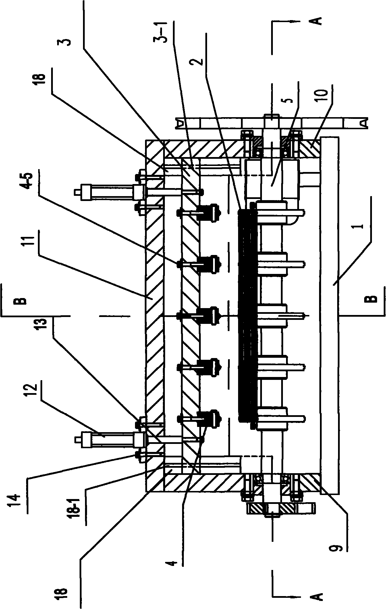
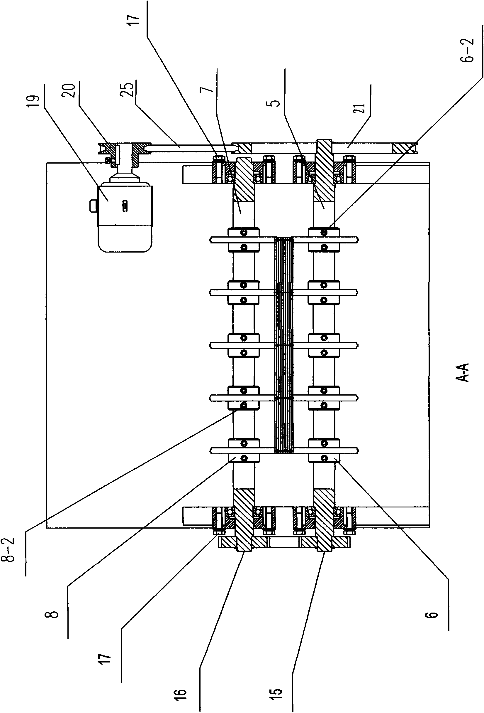
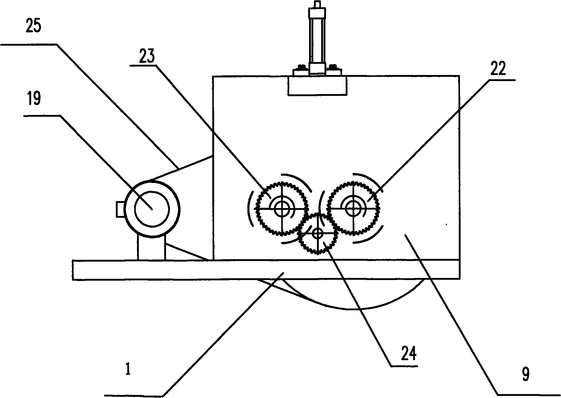
[0031] The present invention will be further described below in conjunction with the accompanying drawings and specific embodiments, but not as a limitation of the present invention. Such as Figure 1-8As shown, a three-way rolling riveting equipment for cross-flow fan blades includes a base 1, a rolling riveting system, a fixing and driving system, a guiding system, and a conduction system. The rolling riveting system includes a roller row, and the roller row is arranged in parallel with the base 1. The cross-flow blade is the impeller 2, and the roller row includes an upper roller row 3, a lower front roller row 5 and a lower rear roller row 7; the upper roller row 3 is arranged directly above the impeller 2 to be processed, and the upper roller row 3 is provided with The upper riveting hob unit with the hob mouth vertically downward, the upper riveting hobs 4 are evenly distributed in the horizontal direction on the upper roller row 3; The two sides of the vertical surface...


PUM


Abstract

The invention discloses three-directional roll riveting equipment of a through-flow fan blade, and belongs to the technical field of the roll riveting equipment of the through-flow fan blade. The three-directional roll riveting equipment comprises a base, a roll riveting system, a fixing and driving system, a guiding system and a conduction system, wherein the roll riveting system comprises a roller row; the roller row is arranged parallel to the base and comprises an upper roller row, a lower front roller row and a lower rear roller row; the upper roller row is arranged over a machined blade wheel and is provided with an upper roll riveting hob set of which a hob edge is vertically downward; the lower front roller row and the lower rear roller row are symmetrically arranged at two sides of a vertical plane on which a center line of the machined blade wheel is positioned and are provided with a lower front roll riveting hob set and a lower rear roll riveting hob set of which hob edges are obliquely upward respectively; and the upper roll riveting hob set, the lower front roll riveting hob set and the lower rear roll riveting hob set form a three-directional roll riveting structure. During machining, the blade wheel is uniformly stressed in three directions so as to ensure that machining pressure is always aligned with the center, the coaxial heights of central discs of the blade wheel are consistent, and the blade wheel is prevented from performing circular runout.

Description

technical field [0001] The invention relates to rolling riveting equipment for cross-flow fan blades, in particular to a mechanical three-way rolling riveting device for metal cross-flow fan blades, and belongs to the technical field of rolling riveting equipment for cross-flow fan blades. Background technique [0002] The metal cross-flow fan blade is the core component of the cross-flow fan. It consists of several metal blades and 2 or more middle plates. The metal blades are inserted into the slots evenly distributed around the middle plate, and then rolled and squeezed by rolling riveting equipment. , so that the middle plate and blades are compressed and fixed. The usual rolling riveting forming equipment mainly includes the rotating structure of the rolling riveting shaft and the hob propulsion device. When in use, the hob is manually pushed to squeeze the middle plate, the processing efficiency is low, and the radial runout of the impeller is difficult to control. ...

Claims


Application Information

Patent Timeline
IPC IPC(8): B21D39/00B21D37/00
Inventor 吴建清李福义
Owner 宁波市天超通风设备有限公司
Learn More