Transmission shaft spacing mechanism for wire rewinding machine

A technology of limit mechanism and transmission shaft, applied in thin material handling, conveying filamentous materials, transportation and packaging, etc., can solve the problems of big safety hazard, golden hook, easy occurrence of wire jamming, etc., to avoid radial runout Effect

Active Publication Date: 2011-10-26
江苏省电力公司太仓市供电公司 +3
View PDF8 Cites 2 Cited by
  • Summary
  • Abstract
  • Description
  • Claims
  • Application Information

AI Technical Summary

Problems solved by technology

However, in the first wire take-up method, the old wires are collected by manpower to be wound on the upper wire coil, which is easy to cause the wire coils to be loose, warped and golden hooked, and the floor space is relatively large. Due to the uneven and loose winding of the old wires during recycling, it is easy to cause wire jamming and other phenomena; the second winding method is due to the small size of the special coil, and the old wires need to be cut and replaced after receiving them to a certain extent, and the effective use length of the old wires is greatly shortened. , and the operator controls it in the cab, which has great potential safety hazards; the third wire take-up method is generally not used in the construction of distribution network lines due to the investment cost of tension machinery and the large area occupied by the tension field layout.

Method used


Image

  • Transmission shaft spacing mechanism for wire rewinding machine
  • Transmission shaft spacing mechanism for wire rewinding machine
  • Transmission shaft spacing mechanism for wire rewinding machine

Examples


Embodiment Construction

[0016] The present invention will be further described below in conjunction with accompanying drawing and embodiment:

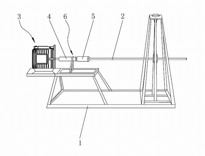
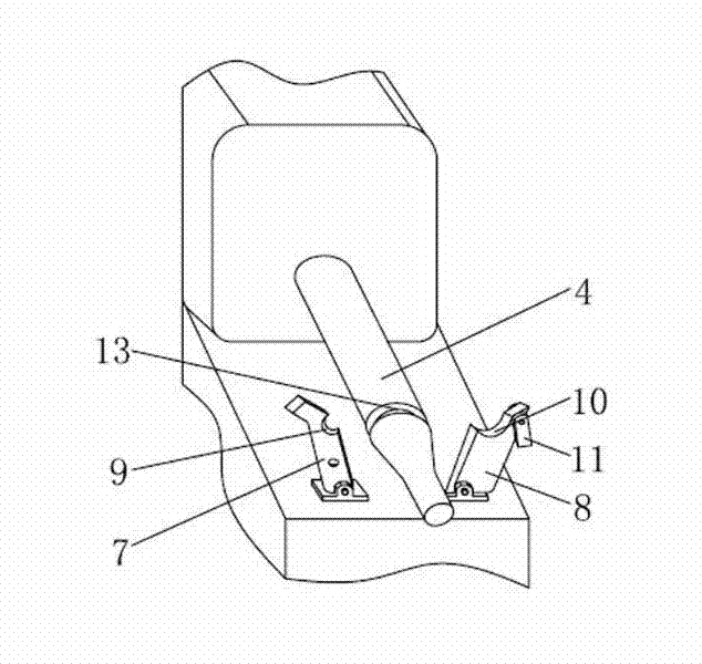
[0017] Such as figure 1 A new type of wire take-up machine is shown, which includes: a frame 1, a rotating shaft 2 arranged on the frame 1 for installing a reel, a driving part 3 arranged on the frame 1 for driving the rotating shaft 2 to rotate, driving Part 3 generally chooses to drive the motor. The driving part 3 drives the rotating shaft 2 to drive the reel to rotate. The output end of the driving part 3 is connected with a transmission shaft 4 , and the transmission shaft 4 is connected with the rotating shaft 2 through a coupling 5 . The transmission shaft 4 is provided with a groove 13 that cooperates with the first limiting block 7 and the second limiting block 8 .

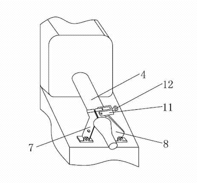
[0018] The frame 1 is provided with a limiting mechanism 6 for limiting the transmission shaft 4, the limiting mechanism 6 includes a first limiting block 7 and a second limiting bloc...


PUM


Abstract

The invention relates to a transmission shaft spacing mechanism for a wire rewinding machine. The wire rewinding machine comprises a frame, a rotating shaft which is arranged on the frame and used for assembling a wire coil, and a drive part which is arranged on the frame and used for driving the rotating shaft to rotate, wherein the drive part drives the rotating shaft to drive the wire coil to rotate, and is connected with a transmission shaft; the transmission shaft is connected with the rotating shaft through a coupler; the frame is provided with a spacing mechanism for spacing the transmission shaft; the spacing mechanism comprises a first spacing block and a second spacing block; a first notch part is formed on the first spacing block; a second notch part is formed on the second spacing block; the first notch part and the second notch part are oppositely arranged; and when the first spacing block is matched with the second spacing block, the transmission shaft simultaneously passes through the first notch part and the second notch part. By utilizing the transmission shaft spacing mechanism, the rotating range of the transmission shaft is limited through the spacing part, and the radial runout of the transmission shaft in the turning process can be effectively avoided.

Description

technical field [0001] The invention relates to a novel transmission shaft limit mechanism of a wire take-up machine. Background technique [0002] In recent years, with the rapid development of the economy, the transformation and upgrading of the power grid has become increasingly frequent. With the gradual increase of the company's urban network and rural network reconstruction projects, the number of old conductors removed is also increasing. Generally speaking, when the old wires are pulled down, they are treated as discarded, and some reusable old wires are only treated as waste materials, resulting in a large amount of waste of resources. [0003] In order to improve the situation of resource reuse, the old wires in the project are recycled to solve the problem of low voltage in rural areas. At present, there are the following wire take-up methods: first, take up the wire through a winch mill tractor and a hoist; second, take up the wire through the rear wheel of the...

Claims


Application Information

Patent Timeline
IPC IPC(8): B65H54/40
Inventor 陆赟朱利军
Owner 江苏省电力公司太仓市供电公司
Why Eureka
Try Eureka