Test system for vertical compression power generation module

A technology of power generation module and test system, applied in electric power measurement through current/voltage, multi-tester circuit, generator/motor, etc., can solve the problem of high frequency, small pressure value, structure and material process optimization and provide effective reference, etc. problem, to achieve the effect of high test accuracy, convenient operation and wide test range

Pending Publication Date: 2021-09-21
CHONGQING UNIV OF ARTS & SCI
View PDF2 Cites 2 Cited by
  • Summary
  • Abstract
  • Description
  • Claims
  • Application Information

AI Technical Summary

Problems solved by technology

[0004] Patent No. 201711359541.3, patent name "A Piezoelectric Component Power Generation Capability Test System" Although the invention patent mentions the ability to measure power generation performance, its excitation source is a piezoelectric signal generator, which has the characteristics of high frequency and small pressure value , therefore, the test results of its power generation capacity are very different from the power generation capacity in low-frequency, high-pressure scenarios such as walking and tire extrusion; "Taiwan" mentioned to test the power generation performance of the gyromagnetic piezoelectric material, but it can only test the voltage value according to the oscilloscope, and cannot obtain the instantaneous current and pressure values, so that the correspondence between the current, voltage and pressure cannot be obtained. relationship, cannot accurately evaluate the pros and cons of piezoelectric components, and cannot provide effective reference for structure and material process optimization
Therefore, there is a lack of equipment in the prior art that can effectively and accurately measure pressure generating components

Method used


Image

  • Test system for vertical compression power generation module
  • Test system for vertical compression power generation module
  • Test system for vertical compression power generation module

Examples


Embodiment

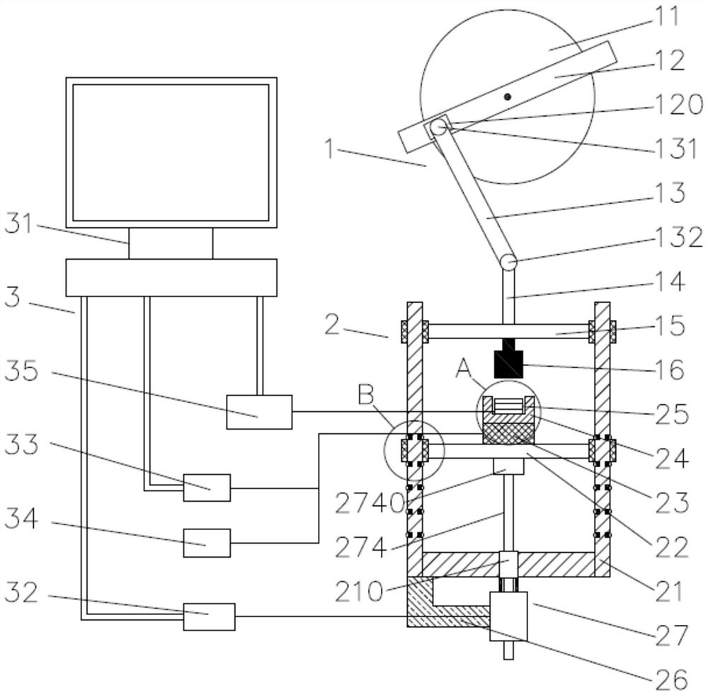
[0031] like Figure 1 ~ 4As shown, a vertical pressure power generation module test system, comprising reciprocating press assembly 1, lifting test assembly 2, and monitoring device 3; lifting test assembly 2 is disposed at the lower end of the reciprocating stamping assembly 1; reciprocating press assembly 1 including rotation The disk 11, the fixing rod 12, the first connecting rod 13, the second connecting rod 14, the first slip plate 15, and the impact hammer 16, the rotary disk 11 is fixedly disposed with a fixing bar 12 and the center of the fixed bar 12 and the rotary disk 11 The center is the same point, and the rotating disk 11 is left away from one side end surface of the fixing rod 12 to set a drive motor (the axis of the output shaft of the drive motor is common in the axis of the rotary disk 11, and the figure is not drawn, according to the art in the art Set), used to control the rotary disc 11, the drive motor is electrically connected to the monitoring device 3; the...


PUM


Abstract

The invention provides a test system for a vertical compression power generation module. The test system comprises a reciprocating stamping assembly (1), a lifting test assembly (2) and monitoring equipment (3), the lifting test assembly (2) is arranged at the lower end of the reciprocating stamping assembly (1); the reciprocating stamping assembly (1) comprises a rotating disc (11), a fixing rod (12), a first connecting rod (13), a second connecting rod (14), a first sliding plate (15) and an impact hammer (16). The lifting testing assembly (2) comprises a supporting frame (21), a second sliding plate (22), a pressure sensor (23), a module container (24), a pressure testing module (25), an L-shaped connecting rod (26) and a lead screw motor (27). The system is controllable in pressure intensity, good in repeatability, capable of accurately measuring the pressure power generation module under the conditions of low frequency and high pressure value, and wide in measurement range; and meanwhile, the system can measure values of current, voltage and pressure changing along with time in real time, and analysis of the performance of the pressure power generation assembly is facilitated.

Description

Technical field [0001] The present invention relates to the field of pressure generating technology, and more particularly to a vertical pressure power generation module test system. Background technique [0002] Currently, for some moving parts, it produces mechanical energy during operation, for example, vehicle tires are deformed during the rotation process; the pedestrians will generate mechanical energy during walking, resulting in mechanical energy; In the prior art, whether it is a shoe, or the mechanical energy generated by the tires, the energy of white is lost in the air, resulting in waste of energy. [0003] Pressure power is a power generation technology that converts mechanically converted into electrical energy, which can effectively convert the mechanical energy generated by the vehicle tire or the bottom of the shoe by pressure generating technology (such as piezoelectric ceramics, Faraday generators, etc.) to achieve power generation. Provide energy for communic...

Claims


Application Information

Patent Timeline
Patent Type & Authority Applications(China)
IPC IPC(8): G01R21/06G01R19/00G01R15/12H02N2/18
CPCG01R21/06G01R19/00G01R15/12H02N2/18
Inventor 程江唐华李璐
Owner CHONGQING UNIV OF ARTS & SCI
Why Eureka
Try Eureka