Adjustable footrest and footrest designing system

A technology for designing systems and pedals, applied in special locations of vehicles, transportation and packaging, vehicle components, etc., can solve the problems of delayed product development cycle, subjective evaluation of human-machine comfort, waste of development costs, etc., to reduce positive development. risk, improve human-machine comfort, and speed up the development cycle

Inactive Publication Date: 2011-04-27
CHERY AUTOMOBILE CO LTD
View PDF5 Cites 14 Cited by
  • Summary
  • Abstract
  • Description
  • Claims
  • Application Information

AI Technical Summary

Problems solved by technology

At present, when automobile manufacturers develop the pedal rest, they use some empirical data or the data obtained from the measurement of the pedal rest of competing models to carry out ergonomic layout. This method of relying on experience and reverse layout has no effect on the comfort Subjective evaluation often leads to deviations, and it cannot take into account the differences in human body size in different countries and age groups.
Changing the plan after the trial production of the vehicle reveals ergonomic problems will delay the product development cycle and result in waste of development costs

Method used


Image

  • Adjustable footrest and footrest designing system
  • Adjustable footrest and footrest designing system
  • Adjustable footrest and footrest designing system

Examples


Embodiment 1

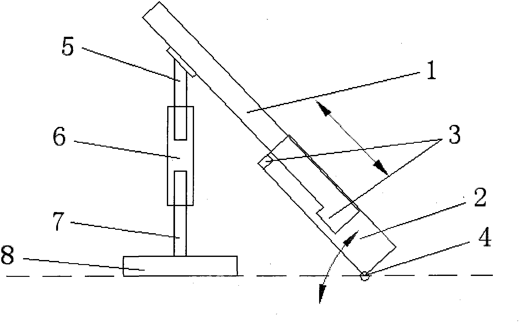
[0018] Such as figure 1 As shown, the adjustable rest pedal of this embodiment includes a pedal arm and a connecting rod. The pedal arm is composed of two sub-pedal arms 1, 2 movably socketed together, and the ends of the two sub-pedal arms 1, 2 are limited. Position card block 3, roller 4 is installed on the bottom of sub-pedal arm 2 located below; the connecting rod is composed of three sub-connecting rods 5, 6, 7 threaded together, and the top of sub-connecting rod 5 is hinged with the pedal arm , the bottom of the connecting rod 7 is fixed with a base 8; the connecting rod 5 at the top and the connecting rod 7 at the bottom are screw rods with opposite thread directions; the connecting rod 6 in the middle is a cylindrical structure with threads inside . When the connecting rod 6 in the middle part is rotated, the connecting rod 5 and 7 in the top and the bottom can be adjusted to extend into the depth of the connecting rod 6 in the middle part, thereby adjusting the lengt...

Embodiment 2

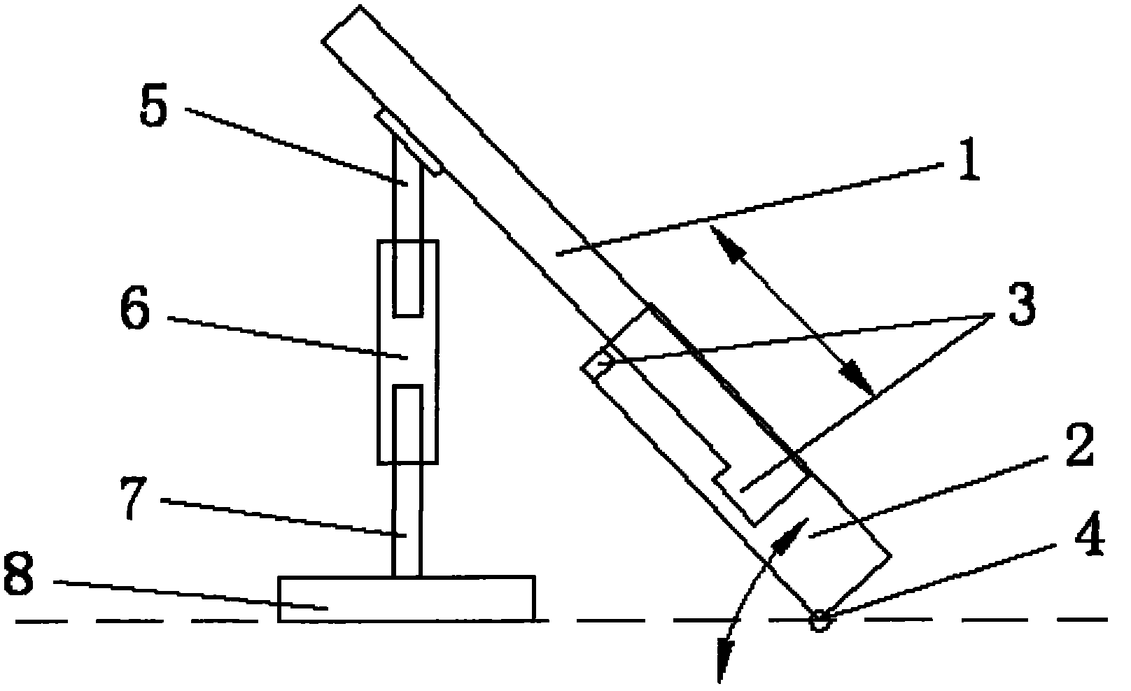
[0022] The difference from Example 1 is that the method of adjusting the length of the connecting rod in this embodiment is as follows: the connecting rod is composed of three sub-connecting rods, of which the top sub-connecting rod is a screw; the middle sub-connecting rod is a barrel with threads inside Shaped structure; the connecting rod at the bottom is connected with the connecting rod at the middle through bearings and can rotate freely. When the sub-link at the middle part is rotated, the depth to which the top sub-link extends into the sub-link at the middle can be adjusted, thereby adjusting the length of the connecting rod and changing the angle of the pedal arm.


PUM


Abstract

The invention provides an adjustable footrest and a footrest designing system applying the same, aiming at improving the man-machine comfort level of the footrest. The adjustable footrest comprises a footrest arm and a connecting rod, wherein the top of the connecting rod is articulated with the footrest arm, the bottom of the connecting rod is fixed with one base, the footrest arm is formed by movably sheathing at least two auxiliary footrest arms together, and the length of the connecting rod is adjustable. In the footrest designing system applying the adjustable footrest, the base of the adjustable footrest is fixed on a platform, which is provided with a car seat opposite to the adjustable footrest. The adjustable footrest and the footrest designing system can provide the footrests of various sizes and angles in the design stage so as to verify the man-machine engineering performance of the design scheme of a vehicle footrest, thereby quickening development period, saving cost for replacement because of the subsequent problems of trial-produced vehicles, and lowering the risk in the forward development of cars.

Description

technical field [0001] The invention belongs to the technical field of automobile ergonomic design, and in particular relates to an adjustable rest pedal and a design system for the rest pedal. Background technique [0002] With the development of the global automobile market and increasingly fierce competition, human-machine comfort is becoming an important factor affecting user purchase behavior and user satisfaction. The ergonomic performance of vehicles has attracted more and more attention from major automobile manufacturers. At present, when automobile manufacturers develop the pedal rest, they use some empirical data or the data obtained from the measurement of the pedal rest of competing models to carry out ergonomic layout. This method of relying on experience and reverse layout has no effect on the ergonomics Subjective evaluations often lead to deviations, and it is impossible to take into account the differences in body size between countries and age groups. Wai...

Claims


Application Information

Patent Timeline
Patent Type & Authority Applications(China)
IPC IPC(8): B60N3/00
Inventor 曹亮王玉惠
Owner CHERY AUTOMOBILE CO LTD
Why Eureka
Try Eureka