Loading and unloading transport vehicle

A technology of loading and unloading trucks and lifting rods, applied in the direction of lifting devices, etc., can solve problems such as low work efficiency, space occupation, and large production investment, and achieve the effect of simple structure, small overall volume, and reduced cost

Inactive Publication Date: 2011-04-27
NINGBO SOKEN CHEM
View PDF9 Cites 10 Cited by
  • Summary
  • Abstract
  • Description
  • Claims
  • Application Information

AI Technical Summary

Problems solved by technology

[0003] The first is to put these rolled objects on a pallet, and then use a forklift to fork them from one place to another. This method is simple and easy to implement, and has been widely used, but it also has many shortcomings. Rolled objects must be placed on a pallet to be transported by a forklift, which requires the production of many pallets, which requires a large production investment and does not meet the low-carbon requirements; secondly, many pallets seem to take up space when used; In the case of small and high height, it is unsafe to place the roll-shaped objects on the pallet and then use the forklift
[0004] The second is to use a two-wheeled trolley for transportation. This method of transportation requires manpower to transport the rolled objects to the trolley. If the rolled objects are heavy, more than two people are required to cooperate with the operation, and the work intensity is high. , and the work efficiency is low
[0005] The third is to use a clamp-type handling tool, such as the Chinese utility model patent "A Forklift Attachment Barrel Holder" (authorized announcement number: CN2295732Y) whose patent number is ZL97217555.5. You can also refer to the patent number as ZL200820057573.8 The Chinese utility model patent "forklift oil drum clamping device" (authorized announcement number: CN201195683Y), but this kind of handling tool is not good for rolling objects that are prone to slipping between layers, such as handling release film rolls, The clamp is stressed on the outer side of the release film roll. When clamping and lifting, there will be slippage between the outer film and the inner film, which is easy to damage the content of the release film roll. In addition, for roll objects with different diameters, special Suitable grippers are matched, which will inevitably increase the handling cost
[0007] However, the above-mentioned disclosed handling device is more suitable for barrel-shaped objects with raised edges, but because roll-shaped objects do not have edges that can be clamped, they are powerless

Method used


Image

  • Loading and unloading transport vehicle
  • Loading and unloading transport vehicle
  • Loading and unloading transport vehicle

Examples


Embodiment 1

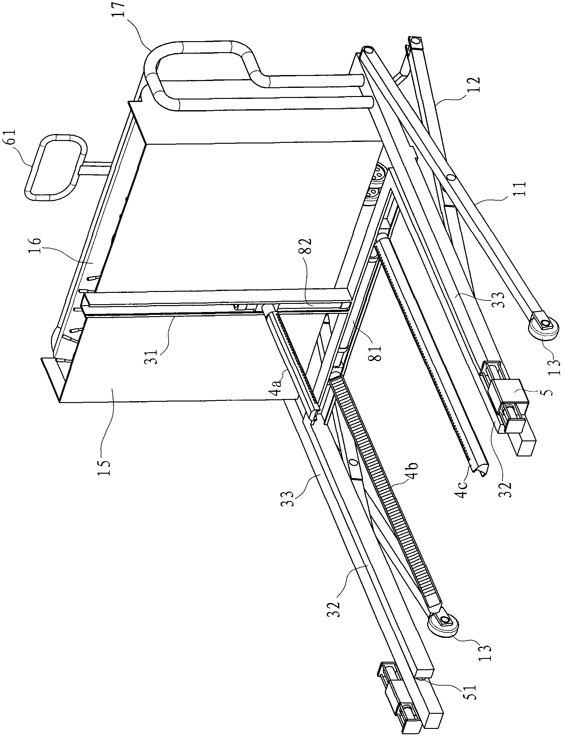
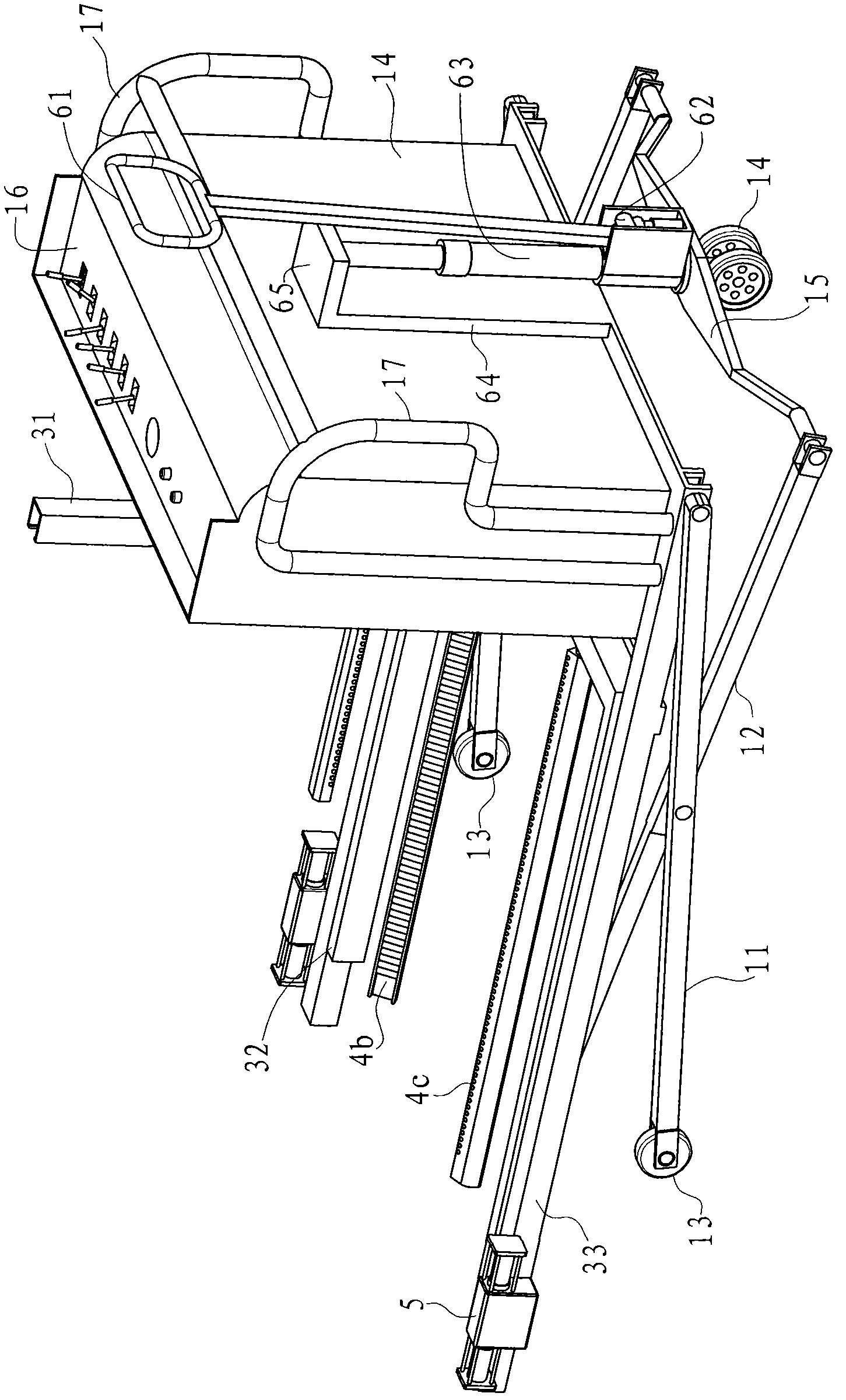
[0043] Example 1, such as figure 1 with figure 2 As shown, the handling truck in this embodiment includes a first lifting rod 11, a second lifting rod 12, a clamping mechanism, a driving mechanism and a controller. There are two first lifting rods 11, which are arranged on the left and right. Each first lifting rod 11 is provided with a front guide wheel 13 at the front end. There are also two second lifting rods 12, respectively corresponding to the middle of the first lifting rod 11 Mutually hinged, see Figure 5 As shown, each second lifting rod 12 has a roller 121 at the front end, a connecting portion 15 is connected between the rear ends of the two second lifting rods 12, and the bottom end of the connecting portion 15 is provided with a rear guide wheel 14 for driving The mechanism is arranged on the connecting portion 15 for driving the clamping mechanism up and down, and the controller has a first control output terminal connected with the driving mechanism.

[0044] Th...

Embodiment 2

[0051] Example 2, such as Picture 11 with Picture 12 As shown, the guide slot bracket 31 in this embodiment includes three sub-guide slot racks intersecting at one point, the angle formed between adjacent sub-guide slot racks is 120°, and the three clamping rods It can be movably installed on the respective sub-guide trough racks.

[0052] The driving source in this embodiment is the motor 7. The motor 7 is capable of forward and reverse rotation. The motor 7 has a tapered output gear 71. The bottom part of each clamping rod is provided with a slider 42 which has an inner screw hole. The motor 7 is in transmission connection with each clamping rod through a transmission mechanism. The transmission mechanism includes three screw rods 43 respectively matched with the slider 42 and three conical input gears 44 meshing with the conical output gear 71, each The screws 43 are rotatably arranged in the guide groove bracket 31, and each conical input gear 44 is arranged at the end of t...

Embodiment 3

[0053] Example 3, such as Figure 13 As shown, the driving sources in this embodiment are the motor 83 and the motor 84, the guide slot bracket 31 is T-shaped, and a slider 42 is provided at the bottom of each clamping rod. The slider 42 has an inner screw hole, and each sliding The block 42 is connected to the motor through the respective screw 43. The screw 43 and the motor are both arranged in the guide slot bracket 313. Of course, if the motor is relatively large, it can also be arranged on the back of the guide slot bracket 31, where the first clamping rod 4a passes The motor 82 is driven, and the lower second clamping rod 4b and the third clamping rod 4c are driven by the same motor 81. Refer to Example 1 for other structures and handling procedures.


PUM


Abstract

The invention discloses a loading and unloading transport vehicle. The transport vehicle comprises two first lifting rods, two second lifting rods, a clamping mechanism, a driving mechanism and a controller, wherein the two first lifting rods are arranged left and right respectively; the two second lifting rods are hinged with the middle parts of the corresponding first lifting rods respectively; the driving mechanism is used for driving the clamping mechanism to ascend and descend; the clamping mechanism also comprises a chassis bracket, a guide groove bracket, three clamping rods and a driving source; the chassis bracket is connected with the power output end of the driving mechanism; the guide groove bracket is arranged on the chassis bracket and can be ascended and descended along with the chassis bracket; the three clamping rods are movably arranged on the guide groove bracket and are perpendicular to the end face of the guide groove bracket; and the driving source is used for driving the clamping rods to move back and forth. Compared with the prior art, the transport vehicle has the advantages that: the three adjustable clamping rods are used for realizing clamping, so the clamping is firm; and because the gap among the clamping rods is adjustable, coiled objects with different diameters can be transported without clamp holders of various specifications, and the cost is greatly reduced.

Description

Technical field [0001] The invention relates to a conveying device. In particular, it relates to a conveying device that can be applied to roll articles, which can be widely used in industries such as tape, film, and papermaking. Background technique [0002] In industries such as tape, film, papermaking, etc., when it is often necessary to transport rolls that are placed upright or lying down, such as paper rolls, film rolls and other materials, three methods are generally used. [0003] The first is to place these rolls on a pallet, and then fork them from one place to another with a forklift. This method is simple and easy to implement and has been widely used, but it also has many disadvantages. First, rolls Objects must be placed on pallets before they can be transported by forklifts. This requires the production of many pallets, which requires a large production investment and does not meet the low-carbon requirements; secondly, many pallets seem to occupy space when used; a...

Claims


Application Information

Patent Timeline
Patent Type & Authority Applications(China)
IPC IPC(8): B66F9/06B66F9/12
Inventor 魏亮
Owner NINGBO SOKEN CHEM
Why Eureka
Try Eureka