
Direct type ultrathin liquid crystal display device

A liquid crystal display device, a direct-type technology, applied in the direction of instruments, nonlinear optics, optics, etc., can solve the problems of large space occupation, difficulty in ultra-thin liquid crystal display device, increase of display device thickness, etc., to reduce thickness and realize ultra-thin Thin, well-conceived effects

Inactive Publication Date: 2011-04-27
东莞帝光电子科技实业有限公司
View PDF0 Cites 9 Cited by
  • Summary
  • Abstract
  • Description
  • Claims
  • Application Information

AI Technical Summary

Problems solved by technology

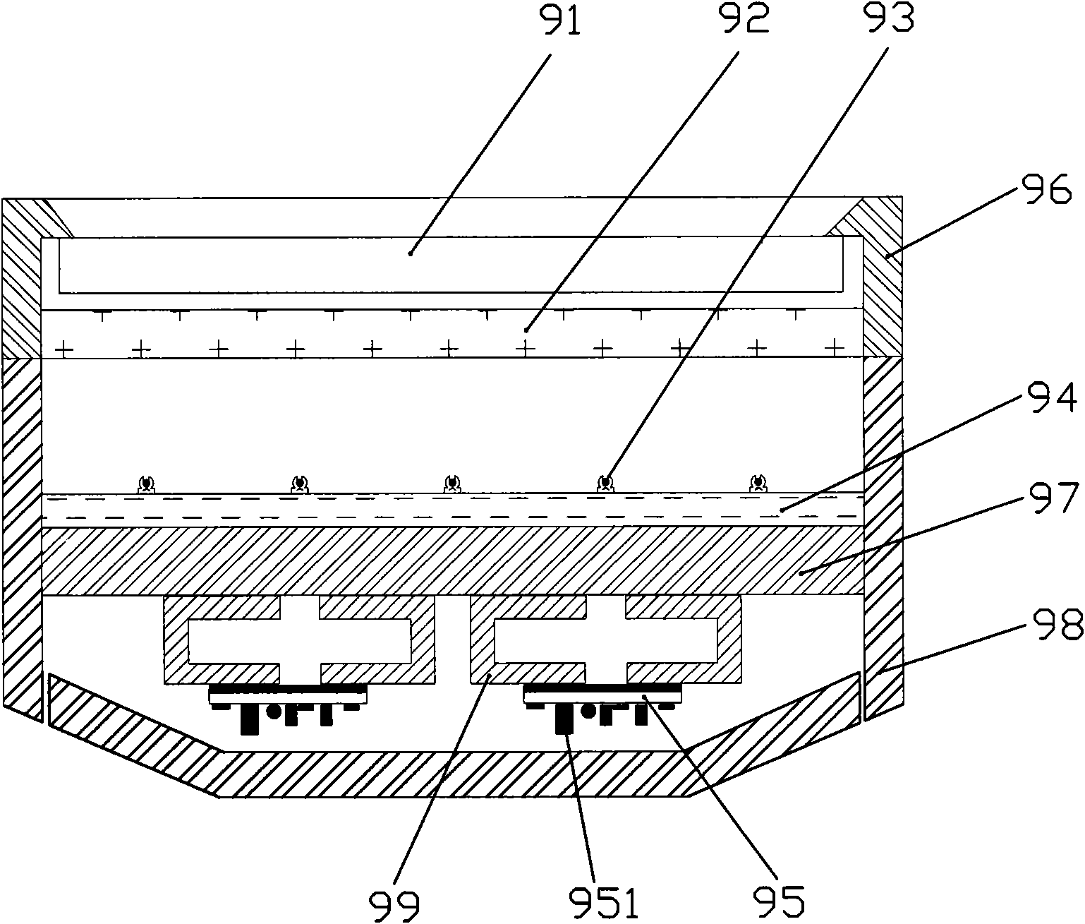
This direct type liquid crystal display device, because PCB board 95 and electronic element 951 on it are arranged in the cavity that partition plate 97 and rear cover 98 form, take up a large space, increase the thickness of display device, be difficult to realize the liquid crystal display device ultra-thin

Method used


Image

  • Direct type ultrathin liquid crystal display device
  • Direct type ultrathin liquid crystal display device
  • Direct type ultrathin liquid crystal display device

Examples


Embodiment 1

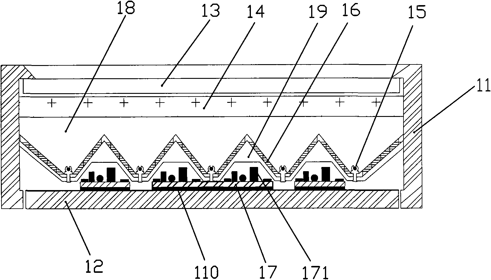
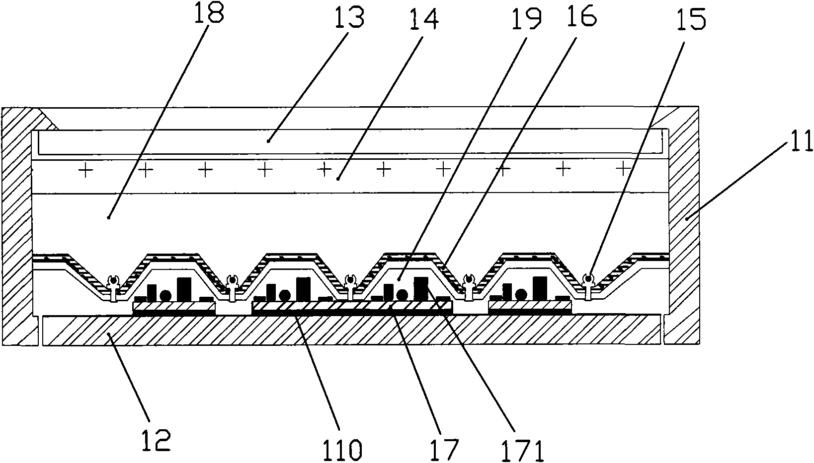
[0025] Such as Figure 2A , Figure 2B with image 3 As shown, a direct-type ultra-thin liquid crystal display device provided by Embodiment 1 of the present invention includes a front cover 11 and a rear cover 12. The front cover 11 and the rear cover 12 cooperate to form a cavity, and the cavity is provided with Display screen 13, diffusion film 14, light source 15, reflection film 16 and PCB board 17, described PCB board 17 is provided with some electronic components 171, and described reflection film 16 is the convex-concave structure of non-planar, and described light source 15 is located at The cavity 18 formed between the reflective film 16 and the diffusion film 14 is located in the recess of the reflective film 16, the PCB board 17 and the circuit components 171 on it are arranged on the reflective film 16 and the back cover 12 and is fixed on the back cover 12 in the cavity 19 formed between them. Compared with the existing direct-type liquid crystal display devic...

Embodiment 2

[0032] Such as Figure 4 As shown, a direct-type ultra-thin liquid crystal display device provided by Embodiment 2 of the present invention includes a front cover 21 and a rear cover 22. The front cover 21 and the rear cover 22 cooperate to form a cavity, and the cavity is provided with Display screen 23, diffusion film 24, light source 25, reflection film 26 and PCB board 27, described PCB board 27 is provided with some electronic components 271, and described reflection film 26 is planar structure, and described light source 25 is located at described reflection The cavity 28 formed between the film 26 and the diffusion film 24 is located on the reflective film 26, and the PCB board 27 and the circuit components 271 on it are scattered between the light sources 25 and located on the reflective film. on the membrane 26. Compared with the existing direct-type liquid crystal display device, in the second embodiment of the present invention, the PCB board 27 and the circuit ele...


PUM


Abstract

The invention is suitable for the display field of a TV, an integrated computer, a display, and the like and provides a direct type ultrathin liquid crystal display device. The direct type ultrathin liquid crystal display device comprises a front cover and a back cover which are matched to form a cavity body; and the cavity body is internally provided with a display screen, a diffusion film, light sources, a reflective film and a PCB (Printed Circuit Board), wherein the PCB is provided with a plurality of electronic elements, and the PCB and circuit elements thereon are arranged between the light sources. Compared with the traditional direct type liquid crystal display device, the PCB and the circuit elements thereon are arranged in a space between the light sources, the concept is skillful, the thickness of the display device is remarkably reduced, and the ultra-thinness of the direct type liquid crystal display device is realized.

Description

technical field [0001] The invention is applied to display fields such as TVs, computer all-in-one machines, monitors, etc., and in particular relates to a direct-down ultra-thin liquid crystal display device. Background technique [0002] Existing liquid crystal display devices are generally divided into two types: side-light type and direct-light type. For small and medium sizes, edge-lit display devices have the advantages of lightness, thinness, and low power consumption; however, with the development of technology, the demand for large-size display devices is increasing, and large-size edge-lit display devices accommodate the number of light sources. Limited, low light utilization efficiency, unable to meet the brightness requirements of large-size liquid crystal display devices. The large-size direct-type display device can accommodate more light sources and has high light utilization efficiency, so it is favored by people. However, the existing large-size direct-type...

Claims


Application Information

Patent Timeline
Patent Type & Authority Applications(China)
IPC IPC(8): G02F1/13
CPCG02F2001/133612G02F1/133605G02F1/133602G02F1/133612
Inventor 宋义苏遵惠
Owner 东莞帝光电子科技实业有限公司
Learn More