Liquid crystal module and liquid crystal display device

A liquid crystal module and accommodating cavity technology, applied in nonlinear optics, instruments, optics, etc., can solve the problems of large light diffusion angle, backlight crosstalk, weak light convergence, etc., and achieve the effect of ultra-thinning

Inactive Publication Date: 2018-04-06
HISENSE VISUAL TECH CO LTD
View PDF6 Cites 8 Cited by
  • Summary
  • Abstract
  • Description
  • Claims
  • Application Information

AI Technical Summary

Problems solved by technology

[0004] The invention provides a liquid crystal module and a liquid crystal display device, which are used to solve the problem that the ultra-thin liquid crystal module has a large light diffusion angle in the process of realizing ultra-multiple partitions, resulting in weak light convergence and backlight crosstalk. Ultra-thin liquid crystal display device realizing high light concentrating effect

Method used


Image

  • Liquid crystal module and liquid crystal display device
  • Liquid crystal module and liquid crystal display device
  • Liquid crystal module and liquid crystal display device

Examples


Embodiment 1

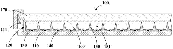
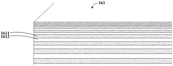
[0028] Embodiment 1 of the present application provides a direct type liquid crystal module, its local structure is as follows Figure 1A shown. A direct-type liquid crystal module 100, including a back plate 110 and a folded edge 111 arranged on the edge of the back plate 110, the back plate 110 and the folded edge 111 form an accommodation cavity 120, and optical The diaphragm group 160, the grid optical component 150 carrying the optical diaphragm group 160, and the light emitting units 140 arranged in an array;

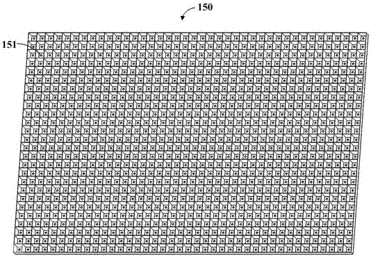
[0029] A sunken groove 151 is formed on the grid optical component 150 corresponding to the position of the light-emitting unit 140, and an opening for accommodating the light-emitting unit 140 is formed on one side of the bottom of the sunken groove 151. On the other side surface, the inner wall of the sinker 151 is a reflective surface. The light-emitting unit 140 is placed in the opening at the bottom of the sinker 151 , and can also play a role in positioning...

Embodiment 2

[0049] Embodiment 2 of the present application also provides a liquid crystal display device, including a panel 170 and the above-mentioned direct-type liquid crystal module 100, the panel 170 is arranged above the direct-type liquid crystal module 100, and the structure and function of the liquid crystal module 100 The interaction and function have been described in detail in the foregoing embodiments, and will not be repeated here.


PUM

PropertyMeasurementUnit
reflectanceaaaaaaaaaa

Abstract

The invention provides a liquid crystal module and a liquid crystal display device. The liquid crystal module is a direct type liquid crystal module and includes an optical film set and a grid-like optical component. The portion, corresponding to a light emitting unit, of the grid-like optical component is provided with a settling tank, the bottom of the settling tank is provided with an opening in which the light emitting unit can be accommodated, the inner wall of the settling tank is a reflection surface, and the disclosed liquid crystal display device includes a panel and the liquid crystal module. The problems that the light diffusion angle in an ultra-multi-subregion liquid crystal module is large, light overlapping is formed in adjacent subregions, and thus light convergence is notstrong is solved, and meanwhile the liquid crystal module is thinned.

Description

technical field [0001] The invention relates to the field of display technology, in particular to a liquid crystal module and a liquid crystal display device. Background technique [0002] With the development of LCD module technology, multi-zone Local Dimming (LD), HDR, and thinning, the liquid crystal display device has higher dynamic contrast, better image quality, and more fashionable appearance. It is also more and more popular among consumers. sought after. When LD technology is introduced into the TV, the backlight of the TV is usually partitioned, with several lights in one area or one light in one area. The main board adjusts the brightness of each area in real time according to the brightness algorithm of the image signal, so as to achieve the backlight. The purpose of real-time brightness adjustment is to improve dynamic contrast and realize energy saving. Due to the limitation of the backlight scheme, on the one hand, the current side light module cannot realiz...

Claims


Application Information

Patent Timeline
Patent Type & Authority Applications(China)
IPC IPC(8): G02F1/1333G02F1/13357
CPCG02F1/133308G02F1/133605G02F1/133606G02F1/133608G02F1/133607
Inventor 翟玉帅高上张志睿杜强张登印
Owner HISENSE VISUAL TECH CO LTD
Why Eureka
Try Eureka