Method and device for manufacturing inductance element

A technology of inductive components and manufacturing methods, which is applied in the direction of electrical components, inductance/transformer/magnet manufacturing, inductance with magnetic cores, etc., can solve the problem of difficulty in forming multiple inductive components in rows 1, inconvenience, and partial winding of the body 112. shift problem

Inactive Publication Date: 2011-04-27
王仕任
View PDF1 Cites 17 Cited by
  • Summary
  • Abstract
  • Description
  • Claims
  • Application Information

AI Technical Summary

Problems solved by technology

[0011] However, the inventors of the present case found that during the manufacturing process of the inductance element 1, only the end portion of the wire pin 111 of the coil 11 is inserted into the slot 35 of the lower mold core 33, so that the coil 11 The winding body 112 is suspended in the lower mold cavity 32 under the condition of weak support, so that the winding body 112 may be shifted during the secondary magnetic powder filling process and the magnetic powder die-casting process The phenomenon, that is, it is difficult to accurately control the coiled body 112 of the manufactured inductance element 1 to be located at the center of the covering block 13, so that the quality and yield of the inductance element 1 will be affected.
In addition, the method of lifting can only

Method used


Image

  • Method and device for manufacturing inductance element
  • Method and device for manufacturing inductance element
  • Method and device for manufacturing inductance element

Examples


Embodiment Construction

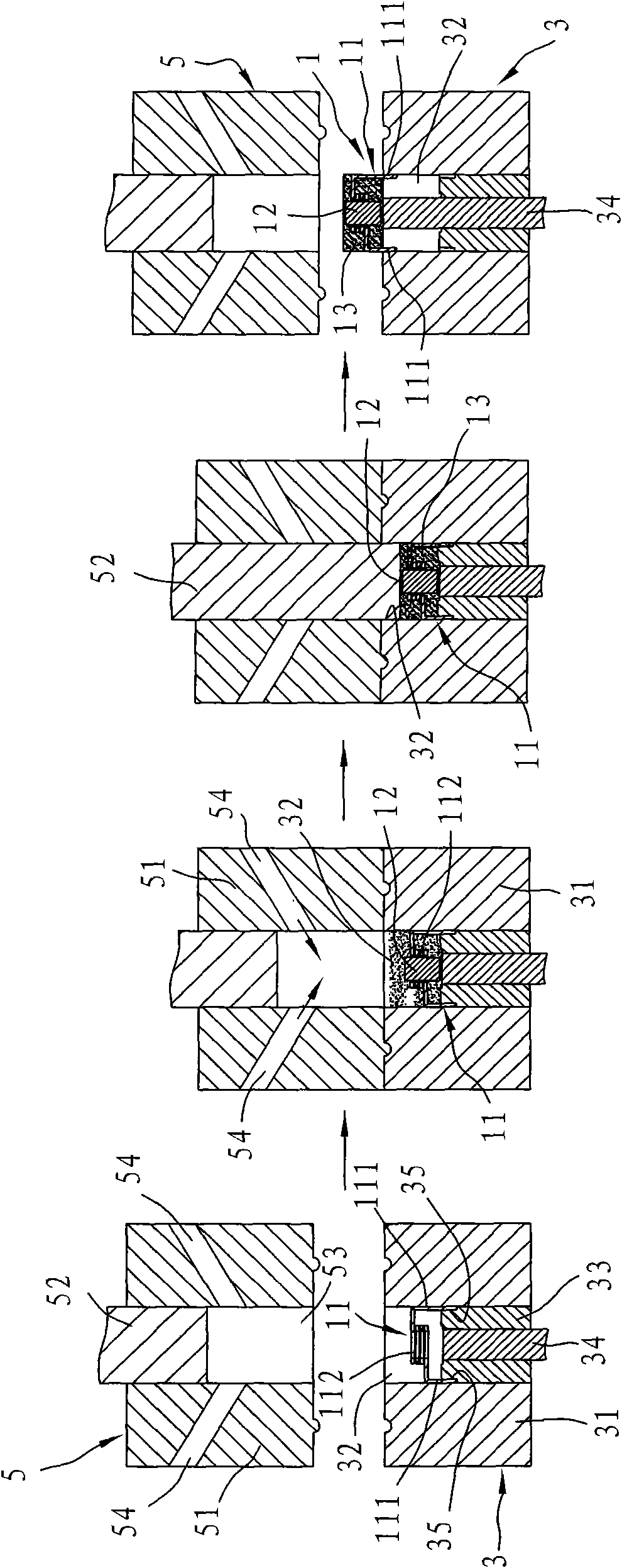
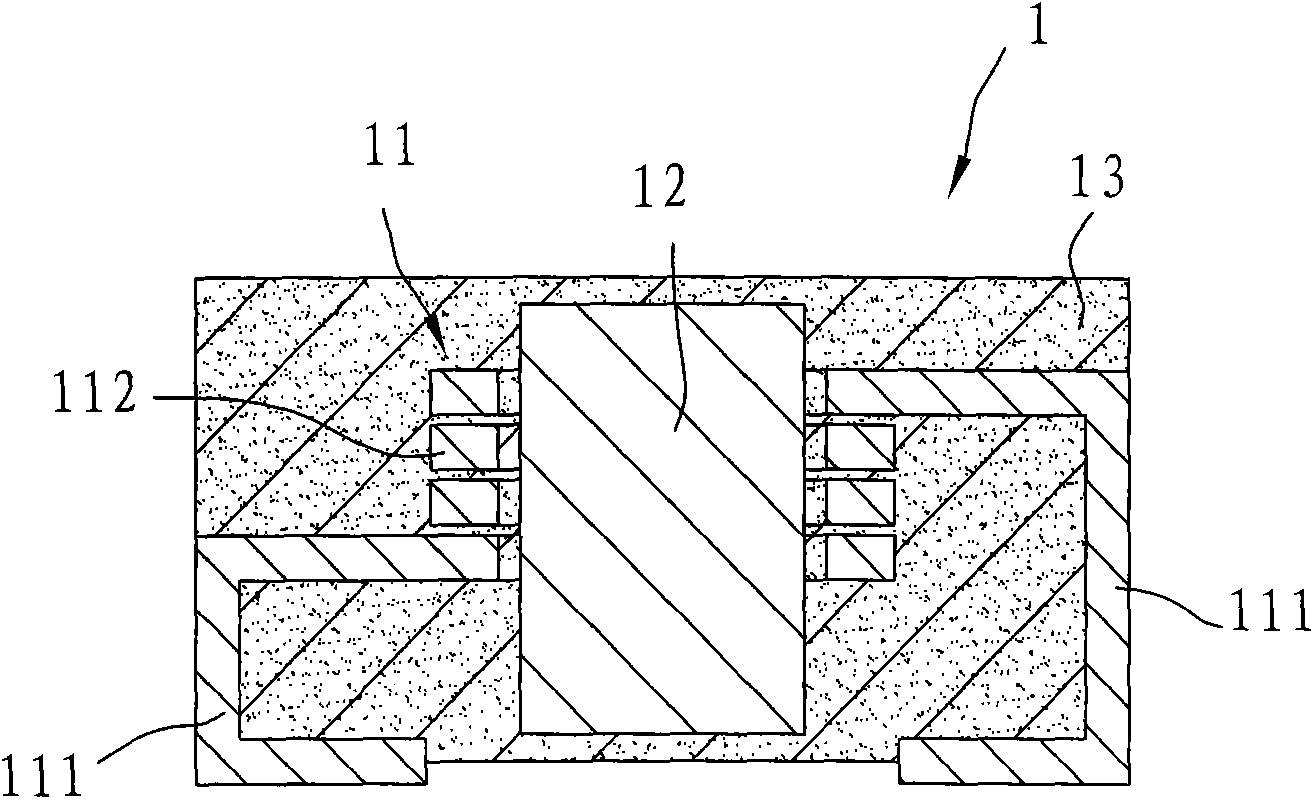
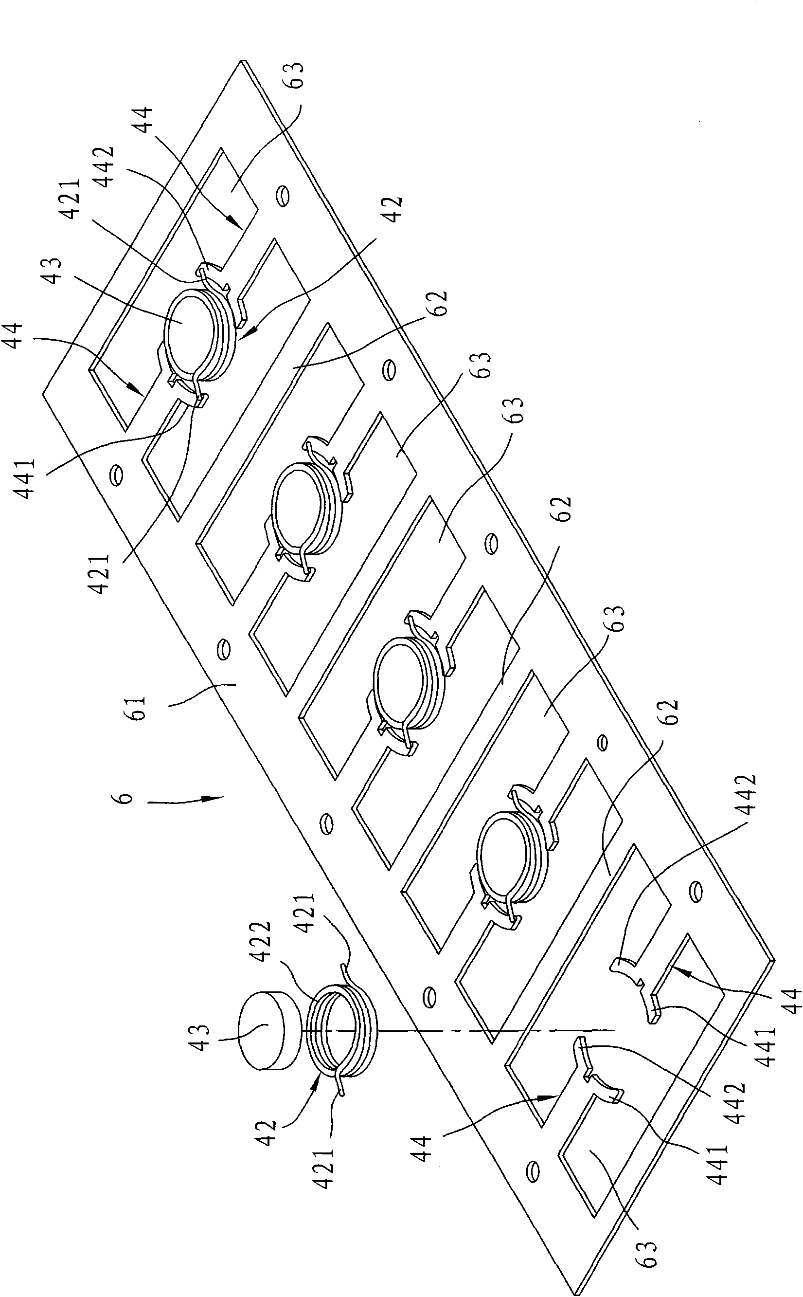
[0041] In order to further explain the technical means and effects that the present invention takes to achieve the intended purpose of the invention, below in conjunction with the accompanying drawings and preferred embodiments, the specific implementation methods and manufacturing methods of the inductive element manufacturing method and its manufacturing device proposed according to the present invention will be described below. , step, structure, feature and effect thereof, detailed description is as follows.

[0042] The aforementioned and other technical contents, features and effects of the present invention will be clearly presented in the following detailed description of preferred embodiments with reference to the drawings. Through the description of the specific implementation mode, when the technical means and functions adopted by the present invention to achieve the predetermined purpose can be obtained a deeper and more specific understanding, but the accompanying ...


PUM


Abstract

The invention relates to a method and a device for manufacturing an inductance element. The method comprises the following steps of: firstly, wrapping and fixing a bent at the periphery of a coil and two terminals which are combined with one another, and clamping and pressing the bent by using a pressing die and a lower die to ensure that the coil is accommodated in an upwards opening powder-filling hole coordinately defined by the pressing die and the lower die; secondly, filling magnetic-conductive powder into the powder-filling hole and completely burying the coil; and finally, performing die pressing on the magnetic-conductive powder in the powder-filling hole by utilizing an upper die to form a cured coated block. Therefore, the coil cannot perform displacement in the magnetic-conductive powder filling process or the powder metallurgy die forming process under the stable support of the bent, so that the quality and yield of manufactured inductance elements can be improved.

Description

technical field [0001] The invention relates to a method for manufacturing an inductance element and a manufacturing device thereof, in particular to a method for manufacturing an inductance element using powder metallurgy molding means and a manufacturing device thereof. Background technique [0002] like figure 1 and figure 2 As shown, it is the No. M278046 "inductance element" patent case of the applicant in Taiwan, China. The disclosed inductance element 1 includes a coil 11, a metal magnetic guide post 12 plugged in the coil 11, and a The coil 11 and the magnetic permeable column 12 are embedded in a flat rectangular block-shaped covering block 13 . The coil 11 has two lead pins 111 respectively protruding out of the covering block 13 and bent and embedded on a bottom surface of the covering block 13, and one for connecting the two lead legs 111 and providing the magnetic conduction The post 12 is plugged and embedded in the coiled body 112 in the cladding block 13 ...

Claims


Application Information

Patent Timeline
IPC IPC(8): H01F17/04H01F41/00H01F27/30H01F27/29H01F41/02
Inventor 王万勋黄明章
Owner 王仕任
Why Eureka
Try Eureka