Frequency conversion

一种频率转换电路、频率的技术,应用在调制转移、电气元件、解调等方向

CN102035474AInactive Publication Date: 2011-04-27NXP BV
10 Cites 8 Cited by

Patent Information

Authority / Receiving Office
CN · China
Patent Type
Applications(China)
Current Assignee / Owner
Publication Date
2011-04-27
Estimated Expiration
Not applicable · inactive patent

Smart Images

  • Figure 1
    Figure 1
  • Figure 2
    Figure 2
  • Figure 3
    Figure 3
Patent Text Reader

Abstract

A frequency conversion circuit (800) is configured to mix a first input signal (RF+,RF-) at a first frequency with a second input signal (LO+,LO-) at a second frequency to provide an output intermediate frequency signal (IFout). The circuit (800) comprises: first and second mixing modules(801a, 801b), each mixing module comprising a voltage to current converter (802a, 802b) configured to receive the first input signal (RF+,RF-) and connected to a Gilbert mixer (803a, 803b)configured to receive the second input signal (LO+,LO-); an intermediate frequency output circuit(804) having inputs connected to receive an intermediate frequency current signal (IF+,IF-) from outputs of each of the Gilbert mixers (803a, 803b) and an output configured to provide the output intermediate frequency voltage signal (IFout), wherein the first and second mixing modules comprise transistors which are complementary to each other.
Need to check novelty before this filing date? Find Prior Art

Description

technical field

[0001] This invention relates to low noise frequency conversion using active Gilbert mixers, and in particular to circuits for performing such frequency conversion. Background technique

[0002] Integrated active Gilbert mixers typically require a DC bias current source at the mixer output. A DC bias current source is also connected to the IF amplifier input and forms a significant source of low frequency noise degrading the signal-to-noise ratio (SNR) of the received signal.

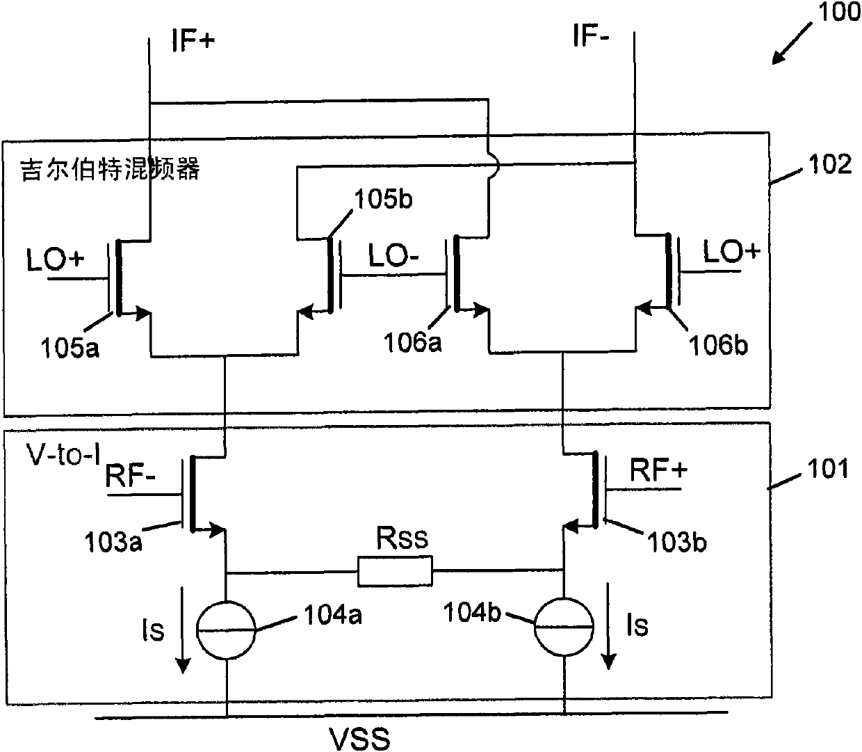
[0003] figure 1 An example of an active Gilbert mixer 102 forming part of the mixer circuit 100 is shown in . The mixer circuit 100 includes a voltage-to-current converter 101 connected to a Gilbert mixer 102 . The voltage-to-current converter 101 comprises a pair of NMOS transistors 103a, 103b whose sources are connected across a resistor Rss and connected to a voltage supply line Vss via respective current sources 104a, 104b, each biased by a transistor 103a, 103b Current Is. Th...

Examples

Embodiment Construction

[0039] A new mixer topology is proposed that addresses the issue of signal-to-noise degradation from IF bias current sources, an exemplary embodiment of this mixer is Figure 8 The mixer circuit 800 is shown. In circuit 800, two complementary mixers 801a, 801b each contribute one-half of the IF output signal, IF+, IF-, while their DC bias currents are reused. A common mode control loop (not shown) may be applied to maintain the correct balance of DC currents for the PMOS mixer section 801a and the NMOS mixer section 801b. The RF input terminals of the PMOS and NMOS mixer sections 801a, 801b are preferably AC coupled. This configuration does not require a DC bias current source to be connected directly to the IF amplifier, thereby reducing or eliminating the noise associated with such a DC bias current source.

[0040] When using two pairs of complementary current sources, an optional additional DC bias current is applied to the voltage-to-current converter (eg Figure 4 sho...