Grip head for an earth boring unit

A technology of clamping head and ground drilling, which is applied in the direction of drill pipe, drill pipe, earth cube drilling, etc., and can solve problems such as liner insertion

Inactive Publication Date: 2011-04-27
迪特马尔 沙伊德尔
View PDF5 Cites 5 Cited by
  • Summary
  • Abstract
  • Description
  • Claims
  • Application Information

AI Technical Summary

Problems solved by technology

[0006] A known problem in this regard in the prior art is that the borehole does not always have a precisely straight course, so that it is sometimes difficult to insert the liner into the borehole produced in the ground after the drill pipe has been raised. middle

Method used


Image

  • Grip head for an earth boring unit
  • Grip head for an earth boring unit

Examples


Embodiment Construction

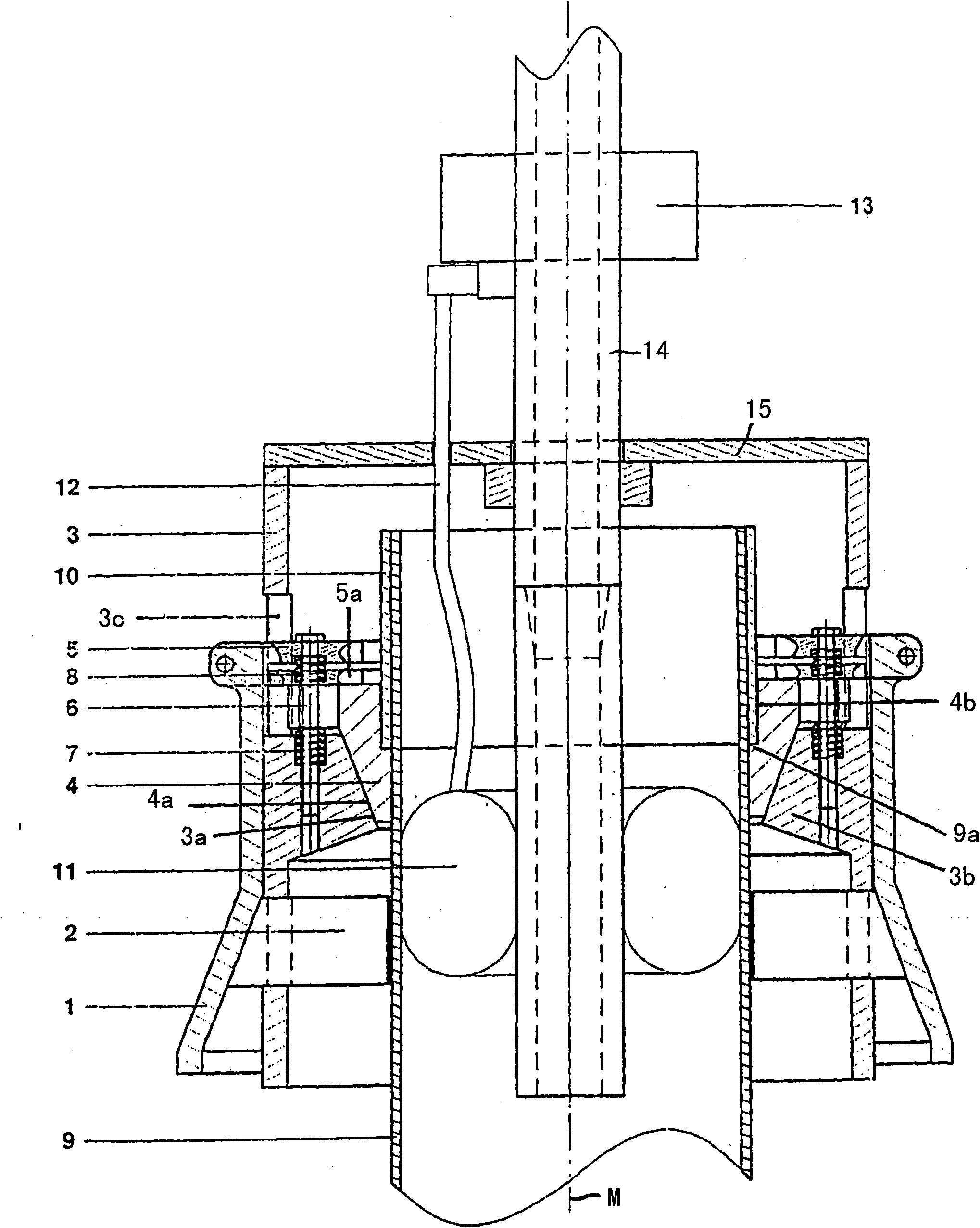
[0024] figure 1 A clamping head according to the invention is shown here in a schematic sectional view, comprising a hollow shaft 3 on which a sleeve 1 is coaxially arranged, which is also called a clamping head cap and its lower funnel Shaped / truncated cone expanding downwards. The funnel-shaped enlarged lower inner wall area of ​​the movable sleeve simultaneously forms an actuating surface for the radially outer ends or inclined surfaces of the individual jaws 2, so that the axial movement of the sleeve downwards causes the individual jaws 2 to automatically Move radially inward. The clamping jaws 2 can then be mounted displaceably on the sleeve 1 and / or on the hollow shaft 3 .

[0025] here in figure 1 Can be seen in the view of a liner 9 inserted in the clamping head according to the invention, wherein the clamping jaws 2 are pressed against the outer surface of the liner 9 from the outside in the radial direction by the downward movement of the outer sleeve 1 and form...


PUM


Abstract

The invention relates to a grip head for an earth boring unit, comprising a hollow shaft (3), wherein a sleeve (1) is arranged coaxially on the hollow shaft (3) to slide relative thereto, said sleeve having at least one end region (1b) widening particularly at the bottom thereof particularly in the form of a cone and at least two clamp jaws (2) which can be displaced radially relative to the hollow shaft (3) are arranged in the hollow shaft (3) and / or on the sleeve (1), comprising stop faces (2b) cooperating with the widening end region (1b), such that on movement of the end region (1b) over the clamp jaws (2) said jaws may be pressed inwards and a first tensioning mechanism and form a first tensioning device for an upper end of a casing (9) which may be introduced from below into the sleeve, in particular such that a cooperation between clamp jaws (2) and casing (9) permits transmission of a torque between ween the hollow shaft (3) and casing (9) and a second tensioning mechanism is provided in the hollow shaft (3), by means of which the introduced / introducible casing (9) may be fixed at the upper rend region thereof in the axial direction, in particular fixing a casing (9) in the axial direction against gravity relative to the grip head, wherein a flush tube (14) of supplying a flushing fluid is arranged coaxially in the hollow shaft (3) and fixed in rotation relative thereto the lower region of which is enclosed by an annular balloon (11) which may be pumped up with a fluid, in particular a liquid.

Description

technical field [0001] The invention relates to a clamping head for an earth-boring device, comprising a hollow shaft, wherein a sleeve is arranged coaxially displaceable relative to it on the hollow shaft, said sleeve having at least one, in particular A downwardly enlarged, in particular conically enlarged, end region, and wherein at least two gripper jaws are mounted radially displaceable relative to the hollow shaft in the hollow shaft and / or on the sleeve, said gripper jaws being On its radially outer end, it has an inclined surface that cooperates with the enlarged end region The clamping jaws can thus be pressed radially inwards by displacement of the end region and form a first clamping means for the upper end region of the liner which can be inserted / inserted into the sleeve from below , in particular so that a torque can be transmitted between the hollow shaft and the liner by co-action between the respective jaws and the liner, and wherein a second clamping mechan...

Claims


Application Information

Patent Timeline
IPC IPC(8): E21B3/02E21B19/07E21B21/10
CPCE21B19/07E21B7/20E21B3/02E21B21/106
Inventor 迪特马尔·沙伊德尔
Owner 迪特马尔 沙伊德尔
Why Eureka
Try Eureka