
High-efficiency labyrinth type air treatment device

An air treatment device, labyrinth technology, applied in electrostatic effect separation, external electrostatic separator, electrode structure, etc., can solve problems such as unsatisfactory quality and poor filtering effect, and achieve the effect of increasing random opportunities and times

Inactive Publication Date: 2011-05-04
吴福吉
View PDF0 Cites 29 Cited by
  • Summary
  • Abstract
  • Description
  • Claims
  • Application Information

AI Technical Summary

Problems solved by technology

[0004] The air of the existing air purifier is quickly discharged from the air outlet through its straight air channel after being sucked in. Therefore, in many cases, the negative (positive) charged air heterogeneous particles and positive (negative ) because there is a long enough distance between the charged dust collecting plates, and the heterogeneous air particles travel in a straight line, so that some negative (positive) charged air heterogeneous particles will be able to escape the positive (negative) charged dust collecting plates smoothly The positive (negative) electric attraction force leaves with the airflow, so the quality of its filtration is not ideal, and the filter device used in general can only filter 0.1μ dust at most, so all kinds of air cleaners currently on the market Due to the poor filtering effect of the air conditioner, most of the filter screens need to be cleaned after several months of use. This phenomenon does not mean that the air quality is good, but that the filtering effect is not good.

Method used


Image

  • High-efficiency labyrinth type air treatment device
  • High-efficiency labyrinth type air treatment device
  • High-efficiency labyrinth type air treatment device

Examples


Embodiment Construction

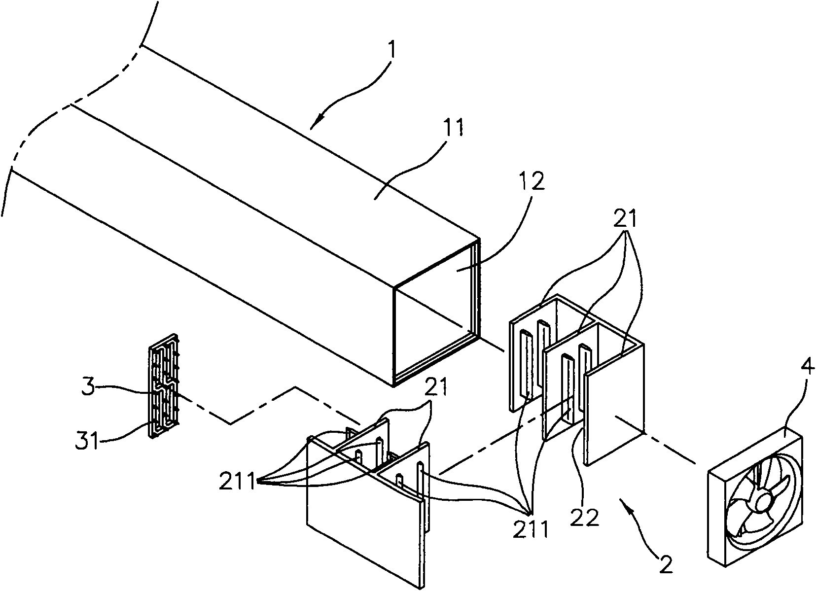
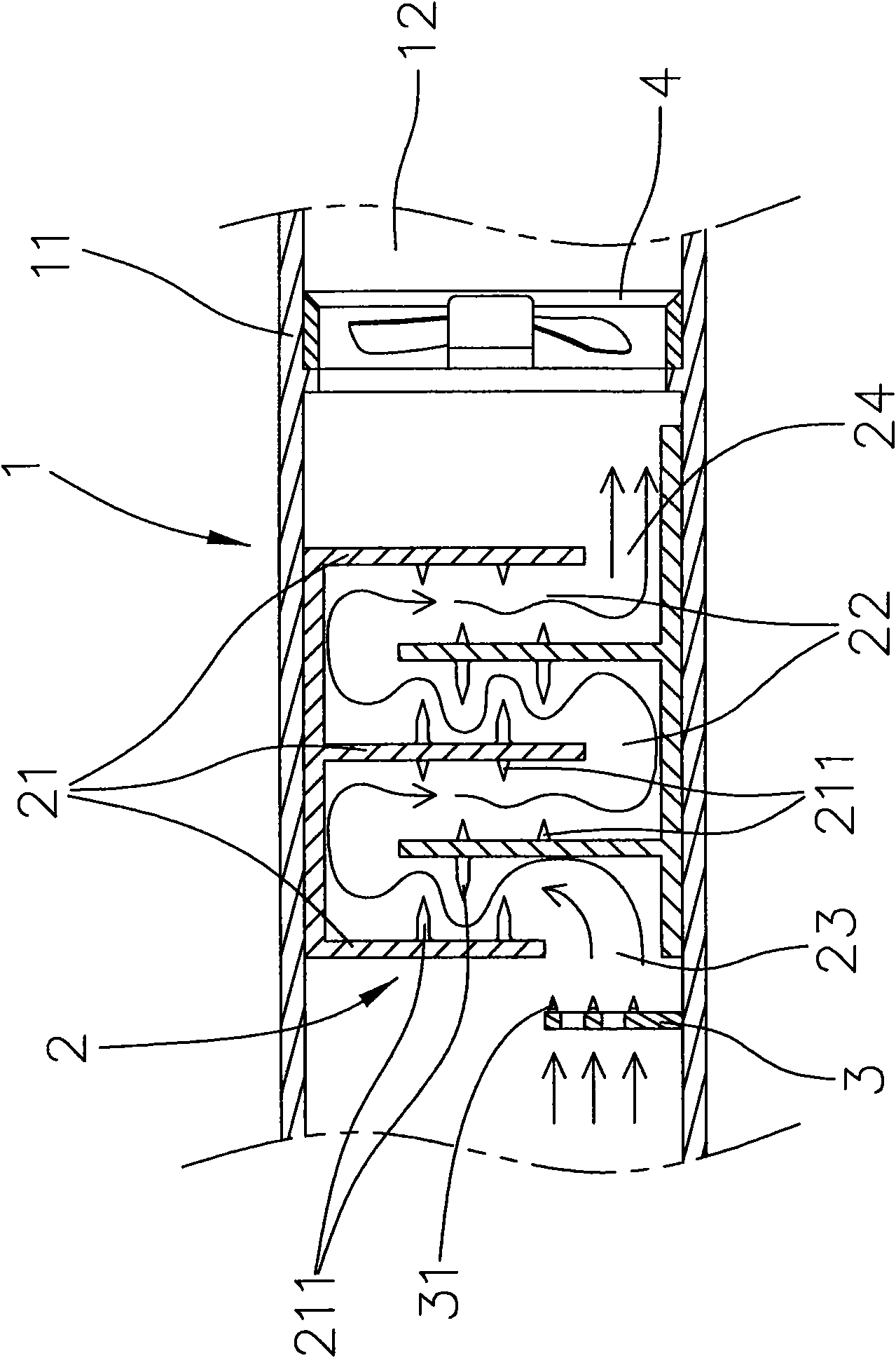
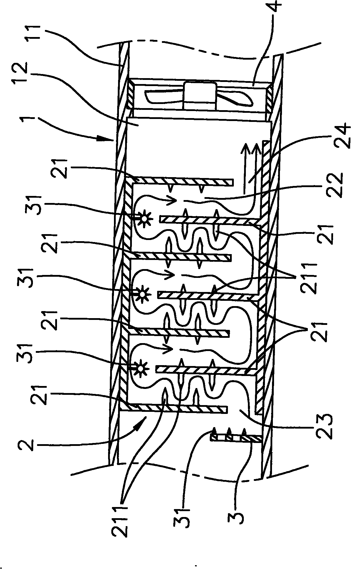
[0034] see figure 1 as well as figure 2As shown, the present invention is a high-efficiency labyrinth air treatment device, which is mainly provided with a dust collection unit 2 in the air duct 12 of the housing 11 of the air treatment device 1, and the dust collection unit 2 is composed of at least one It is composed of dust collecting plates 21 that are arranged in a cross-corresponding manner, and a labyrinth semi-enclosed air flow channel 22 is formed in the dust collecting unit 2, and an air inlet 23 is provided at one end of the dust collecting unit 2. The discharge emission terminal (line) 31 and the fan 4 of the ionization generator, the air ionization generator is an ion generator comprising negative (positive) electricity and a positive (or negative) electrostatic high-voltage discharger... etc., the present invention Take the ion generator 3 of negative (positive) electricity among them as embodiment, the present invention is provided with the discharge emission ...


PUM


Abstract

The invention relates to a high-efficiency labyrinth type air treatment device. The high-efficiency labyrinth type air treatment device is characterized in that a dust collecting unit is arranged in an air duct of a shell of the air treatment device and consists of at least more than one groups of dust collecting plates which are mutually and correspondingly intersected and arranged and charged positively (negatively); a labyrinth-shaped semienclosed air flow channel is formed in the dust collecting unit and is internally provided with a discharge transmitting end (wire) of an air ionization generator and a fan; and further the air is suctioned to be ionized close to the discharge transmitting end (wire) of the air ionization generator by means of the fan so as to enable the heterogeneous particles of the air to be charged positively (negatively), enable the heterogeneous particles charged positively (negatively) of the air to enter the labyrinth-shaped air flow channel in the dust collecting unit, enable the air to generate circuity in the labyrinth-shaped air flow channel in the dust collecting unit to collide with the dust collecting plate charged positively (negatively) and disturb the normal flowing state of the heterogeneous particles of the air, therefore, the purposes of changing the air flowing direction and improving the dust collecting effect of the dust collecting unit are achieved.

Description

technical field [0001] The present invention relates to an air treatment device, in particular to a dust collection unit provided in the air duct of the housing of the air treatment device. Negative) electricity, and form a labyrinthine air flow channel in the dust collection unit, and the discharge emission end (line) and fan of the air ionization generator are provided in the air channel of the air treatment device, Then, using the principle of material inertial motion, relying on the suction airflow generated by the fan to deliberately guide the negatively (positively) charged air heterogeneous particles in the planned semi-closed dust collection unit with positive (negative) charge. The inner wall of the air duct hits the dust collecting plate with positive (negative) electricity in a comprehensive way, so that the heterogeneous particles that have been charged with negative (positive) electricity in the air will have multiple collisions due to the change of the airflow di...

Claims


Application Information

Patent Timeline
IPC IPC(8): B03C3/02B03C3/011B03C3/47
CPCB03C3/09B03C3/368B03C3/41B03C3/47
Inventor 吴福吉
Owner 吴福吉
Learn More