Bucket and operation vehicle

A technology for working vehicles and buckets, which is applied to mechanically driven excavators/dredgers, etc., and can solve problems such as large digging resistance of buckets

Active Publication Date: 2011-05-04
KOMATSU LTD
View PDF8 Cites 3 Cited by
  • Summary
  • Abstract
  • Description
  • Claims
  • Application Information

AI Technical Summary

Problems solved by technology

At this time, a large excavation resistance is generated on the bucket

Method used


Image

  • Bucket and operation vehicle
  • Bucket and operation vehicle
  • Bucket and operation vehicle

Examples


no. 1 approach

[0052]

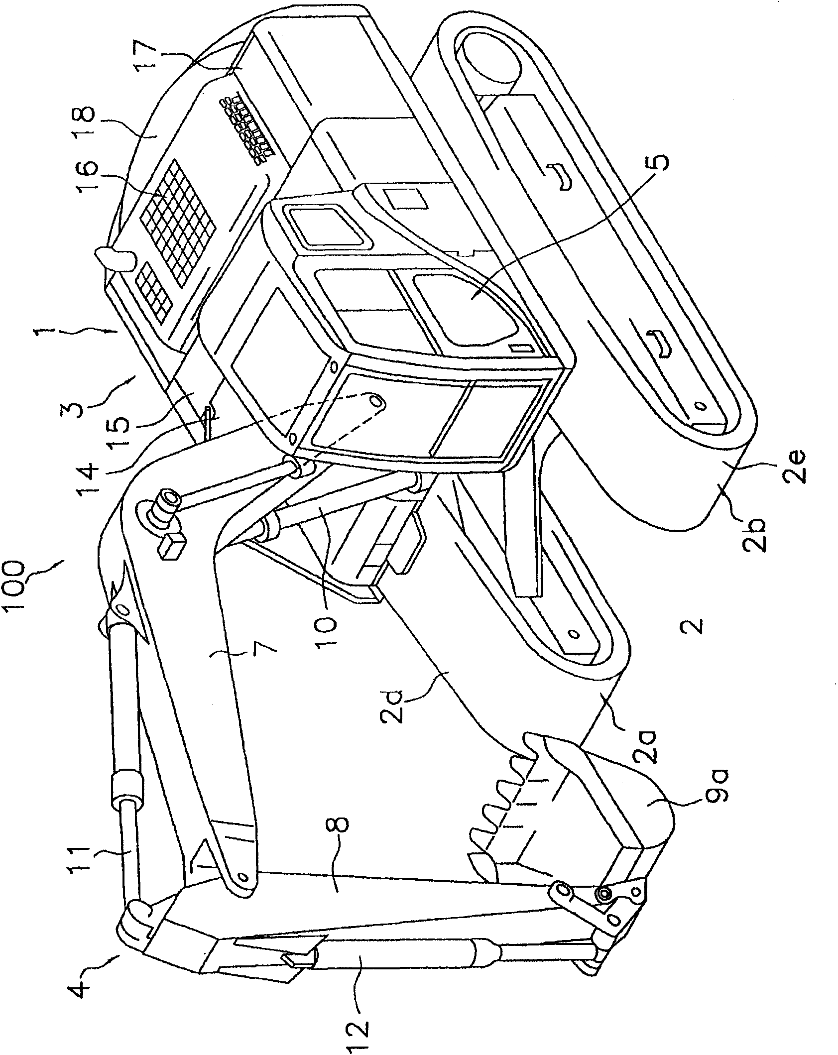
[0053] figure 1 A hydraulic excavator 100 according to a first embodiment of the present invention is shown. This hydraulic excavator 100 has a vehicle body 1 and a work machine 4 .

[0054] The vehicle body 1 has a traveling body 2 and a rotating body 3 . The running body 2 has a pair of running devices 2a, 2b. Each traveling device 2a, 2b has crawler belts 2d, 2e, and drives the hydraulic excavator 100 by driving the crawler belts 2d, 2e with the driving force from the engine. In the description of the overall structure, the front-rear direction refers to the front-rear direction of the vehicle body 1 . In addition, the left-right direction or the side surface refers to the vehicle width direction of the vehicle body 1 .

[0055] The rotating body 3 is mounted on the traveling body 2 . The rotating body 3 is arranged rotatably on the traveling body 2 . In addition, a cab 5 is provided at the front left side of the revolving body 3 . The rotating body 3 has...

no. 2 approach

[0086] Figure 9 A bucket 9b according to the second embodiment of the present invention is shown. In this bucket 9b, the center O11 of the first curvature radius R11 of the first curved surface portion 41 is located outside the bucket 9b similarly to the first embodiment described above. In addition, the tooth tip radius ratio R11 / D11 satisfies the above-mentioned formula 1. However, the first curvature radius R11 is smaller than the tooth tip radius D11. For example, R11=1700mm, D11=2200mm, at this time, the tooth tip radius ratio R11 / D11=0.77. In addition, in a side view, the first curved surface portion 41 is arranged above the reference curved surface S2.

[0087] The other structures are the same as those of the bucket 9a in the above-mentioned first embodiment. The bucket 9b of this embodiment can also achieve the same effect as the bucket 9a of the first embodiment.

no. 3 approach

[0089] Figure 10 A bucket 9c according to a third embodiment of the present invention is shown. In this bucket 9c, the center O21 of the first curvature radius R21 of the first curved surface portion 41 is located outside the bucket 9c similarly to the first embodiment described above. In addition, the tooth tip radius ratio R21 / D21 satisfies the above-mentioned formula 1. However, the first curvature radius R21 is smaller than the tooth tip radius D21. For example, R21=1300mm, D21=2200mm, at this time, the tooth tip radius ratio R21 / D21=0.59. In addition, in a side view, the first curved surface portion 41 is arranged above the reference curved surface S2.

[0090] The other structures are the same as those of the bucket 9a in the above-mentioned first embodiment. The bucket 9c of this embodiment can also achieve the same effect as the bucket 9a of the first embodiment.


PUM


Abstract

The present invention provides a bucket and an operation vehicle. A bottom surface section (32) of the bucket (9) has a first curved surface section (41) and a second curved surface section (42). The second curved surface section (42) is located nearer the back side than is the first curved surface section (41), and is connected to the first curved surface section (41). A second radius of curvature (R2) of the second curved surface section (42) is smaller than a first radius of curvature (R1) of the first curved surface section (41). From a side view, the center of radius of curvature (O1) ofthe first curved surface section (41) is located outside a bucket body (21). Furthermore, from the side view, the first curved surface section (41) is disposed along a reference curved surface (S2) or above the reference curved surface (S2) in a horizontal state where a phantom line (S1) is disposed horizontally and where the bottom surface section (32) is positioned below the phantom line (S1). Moreover, from the side view, a connection section (P2) between the first curved surface section (41) and the second curved surface section (42) is located, in a horizontal state, nearer a lip section(35) than is that portion (P3) of the bottom surface section (32) which is located at the lowest position.

Description

technical field [0001] The invention relates to a bucket and a working vehicle. Background technique [0002] A bucket mounted on a work vehicle has a plurality of teeth, a bracket, and a bucket body. The bucket teeth are arranged on the upper front side of the bucket body. The bracket is provided on the back side of the bucket body. In addition, a hole is provided in the bracket, and the bucket is mounted on the arm by inserting a mounting pin into the hole. Thus, the bucket is rotatably attached to the arm around the attachment pin. [0003] In addition, the bucket body has a box shape with one side open so that sand and soil can be loaded. The bottom portion of the bucket body has a curved shape (see Patent Document (Japanese) Unexamined Patent Publication No. 2003-321848). [0004] When excavating with the bucket, the entire bucket is moved by turning the arm, and the bucket turns around the hole of the bracket. As a result, the tip of the tooth moves along an arc-...

Claims


Application Information

Patent Timeline
Patent Type & Authority Applications(China)
IPC IPC(8): E02F3/40E02F3/32
CPCE02F3/40
Inventor 永田贵则樋口宪一上田匡邦石田耕三伊藤大二郎
Owner KOMATSU LTD
Why Eureka
Try Eureka