A multifunctional drilling rig suitable for silt formation and its construction method

A construction method and multi-functional technology, applied to drilling equipment and methods, drill pipes, drill pipes, etc., can solve problems such as low geological strength of drilling sidewalls, collapse, and difficulty in inserting and pulling out steel casings

Active Publication Date: 2021-06-04
江苏省地质矿产局第三地质大队
View PDF5 Cites 0 Cited by
  • Summary
  • Abstract
  • Description
  • Claims
  • Application Information

AI Technical Summary

Problems solved by technology

[0002] In construction and industrial and mining fields, it is often necessary to drive piles or drill holes. In some poor geological environments, such as silt terrain, the difficulty of drilling construction will increase a lot. The problems that arise include the following: 1. In silt formations , due to the soft texture of the silt, drilling tools are used to directly excavate, and because the strength of the sidewall silt of the well is not high, it will collapse; in this case, the construction personnel will think of steel casing reinforcement, but the traditional steel The casing is only protective, and the cylinder with openings at both ends, when used in the bottom layer of mud, due to the viscosity of the mud, it will be very difficult to insert and pull out the steel casing; 2. Due to the limited length of the steel casing, it cannot Completely insert the mud layer to protect the drilling well. After a certain depth, when the steel casing cannot protect, the geological strength of the side wall of the drilling well is not high, and it is still easy to collapse, and it is difficult to reinforce the side wall of the drilling well.

Method used


Image

  • A multifunctional drilling rig suitable for silt formation and its construction method
  • A multifunctional drilling rig suitable for silt formation and its construction method
  • A multifunctional drilling rig suitable for silt formation and its construction method

Examples


Embodiment Construction

[0037] The directions shown in the accompanying drawings are up, down, left, and right.

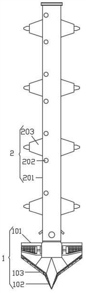
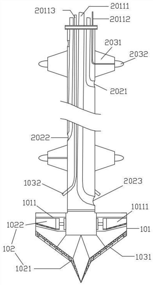
[0038] Such as figure 1 , The multifunctional drilling machine includes a reaming drill bit 1 and a drill rod 2 . The reaming drill 1 includes a drill case 101 , a drill 102 and a water jet assembly 103 , the drill 102 is arranged around the outside of the drill case 101 , and the water jet assembly 103 is arranged outside the drill case 101 and fitted with the drill 102 . The drill rod 2 is arranged on the top of the reaming drill bit 1, and it includes a hollow rod body 201, a connection port 202 and a sealing ring 203. The side wall of the hollow rod body 201. The reaming drill bit 1 has the functions of equidistant drilling and reaming drilling. The drill shell 101 is used to install the drill bit 102 and the water jet assembly 103, and a motor and its control system are also installed inside it to directly drive the drill bit for rotary drilling. contact with the soil, the water ...


PUM


Abstract

The invention discloses a multifunctional drilling rig suitable for silt formations and a construction method thereof. The drilling rig includes a reaming drill bit and a drill rod; wherein the reaming drill bit includes a drill shell, a drill cutter and a water jet assembly, and the drill cutter is arranged on Around the outside of the drill shell, the waterjet assembly is set outside the drill shell and installed in conjunction with the drill; the drill rod is set on the top of the reaming drill bit, including a hollow rod body, a connecting port and a sealing ring, and the connecting port and the sealing ring are evenly arranged On the side wall of the hollow rod body, and the connection port runs through the side wall of the hollow rod body. The method comprises the following steps: construction preparation; lowering the steel casing; reaming bit and water knife assembly work; reaming bit rotary digging; stop rotary digging, inflate the sealed air bag; pump out the mud; deflate the sealed air bag, and continue the rotary digging; Remove and flush reamer; remove steel casing. The multifunctional drill bit of the present invention has the function of reaming holes, which is beneficial to improving the protection strength of the drilling wall after the cement is poured.

Description

technical field [0001] The invention relates to the field of drilling construction, in particular to a multifunctional drilling rig suitable for mud formations and a construction method thereof. Background technique [0002] In construction and industrial and mining fields, it is often necessary to drive piles or drill holes. In some poor geological environments, such as silt terrain, the difficulty of drilling construction will increase a lot. The problems that arise include the following: 1. In silt formations , due to the soft texture of the silt, drilling tools are used to directly excavate, and because the strength of the sidewall silt of the well is not high, it will collapse; in this case, the construction personnel will think of steel casing reinforcement, but the traditional steel The casing is only protective, and the cylinder with openings at both ends, when used in the bottom layer of mud, due to the viscosity of the mud, it will be very difficult to insert and p...

Claims


Application Information

Patent Timeline
Patent Type & Authority Patents(China)
IPC IPC(8): E21B7/00E21B7/28E21B7/20E21B10/32E21B10/61E21B12/00E21B17/00E21B17/18E21B33/12E21B33/13E21B21/00
CPCE21B7/00E21B7/20E21B7/28E21B10/32E21B10/61E21B12/00E21B17/00E21B17/006E21B17/18E21B21/00E21B33/12E21B33/1208E21B33/13
Inventor 许联邵苏文卜成石祥建
Owner 江苏省地质矿产局第三地质大队
Why Eureka
Try Eureka