
Illumination unit for endoscope and endoscope

a technology which is applied in the field of endoscope and endoscope illumination units, can solve the problems of increasing the diameter of the insertion section of the endoscope, and achieve the effect of excellent protection strength

Inactive Publication Date: 2014-10-02
FUJIFILM CORP
View PDF5 Cites 6 Cited by
  • Summary
  • Abstract
  • Description
  • Claims
  • Application Information

AI Technical Summary

Benefits of technology

The invention relates to a compact and protected LED lighting unit that generates a column of light. The protective cover has a certain thickness and is designed to minimize the loss of light. The emission diameter of the fluorescent body is set, the effective diameter of the protective cover is set, and the thickness of the protective cover is set. This results in a lighting unit that is both compact and strong, allowing for effective protection.

Problems solved by technology

However, since the outer diameter of the illumination unit should be increased to obtain illumination light having high intensity, there is a problem in that the diameter of the insertion section of the endoscope is increased.

Method used


Image

  • Illumination unit for endoscope and endoscope
  • Illumination unit for endoscope and endoscope
  • Illumination unit for endoscope and endoscope

Examples


Embodiment Construction

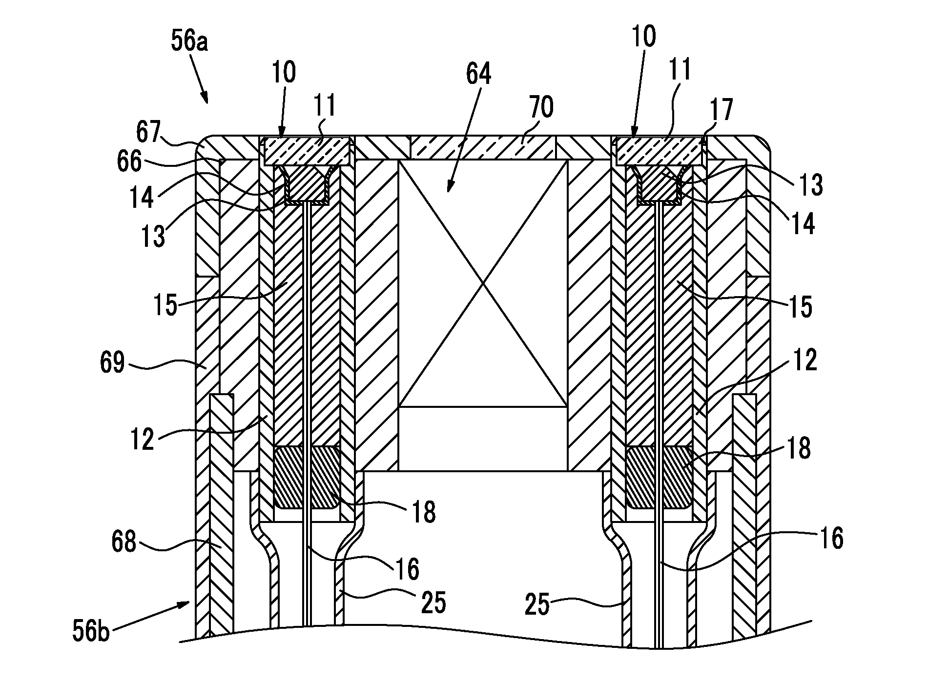
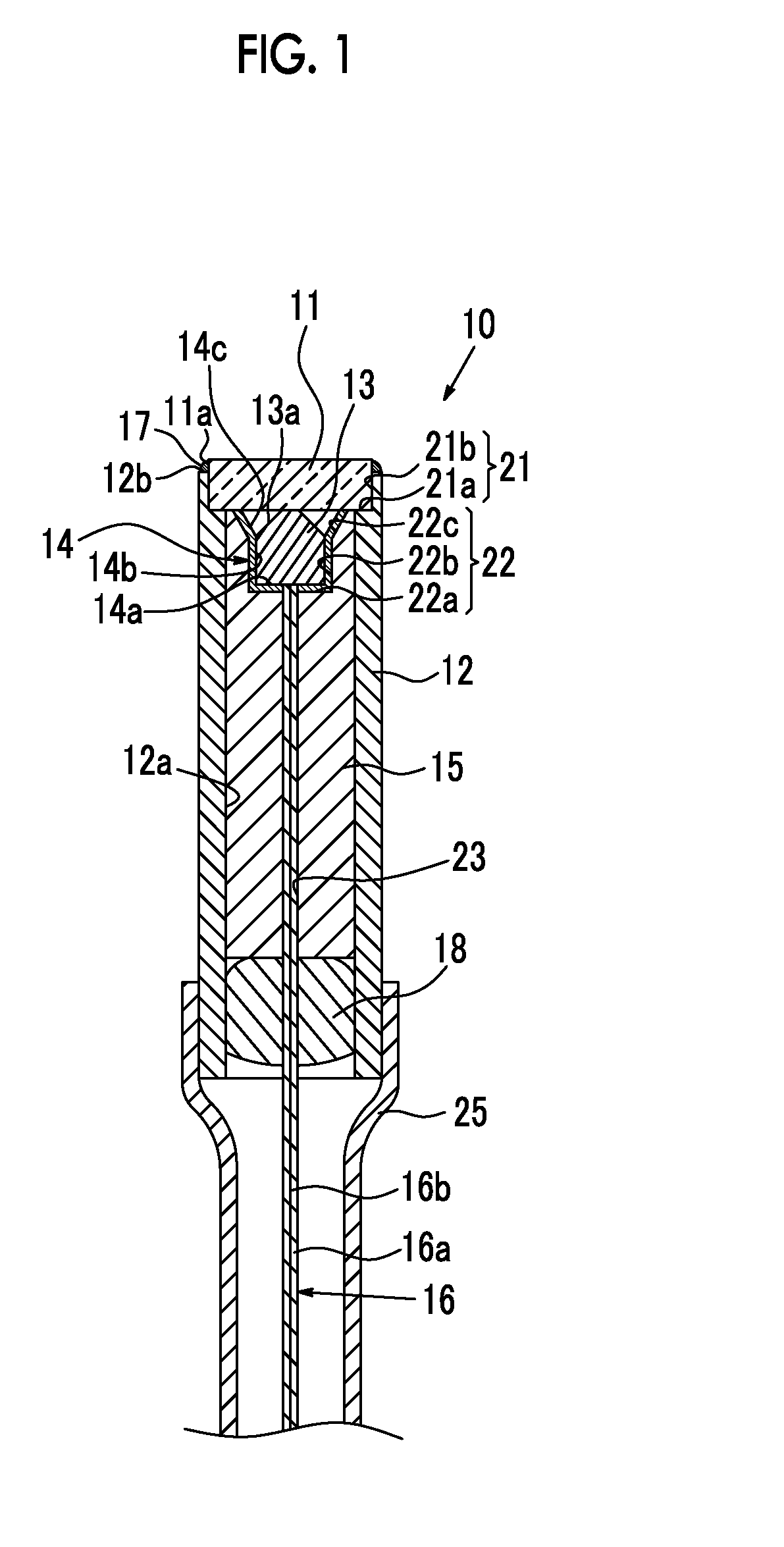
[0024]As shown in FIG. 1, an illumination unit 10 of the invention includes a protective cover 11, a sleeve 12, a fluorescent body 13, a metal reflective film 14, a ferrule 15, and an optical fiber 16 in this order from a tip thereof. A first sealing portion 17 is formed between the protective cover 11 and an upper end (one end) of the sleeve 12, and a second sealing portion 18 is formed between a lower end (the other end) of the sleeve 12 and the ferrule 15. The fluorescent body 13 and the metal reflective film 14 are sealed in the sleeve 12 by these sealing portions 17 and 18.

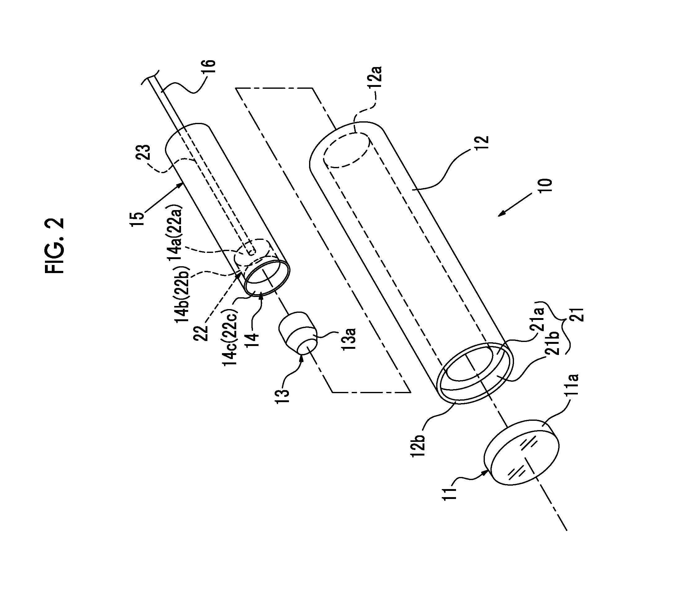
[0025]As shown in FIG. 2, the sleeve 12 is formed in the shape of a cylinder having an inner peripheral surface 12a, and a cover receiving portion 21 on which the protective cover 11 is mounted is formed at one end of the sleeve 12. The sleeve 12 is made of a hard material, such as stainless steel, nickel, copper, a copper-tungsten alloy, a copper-molybdenum composite material, or phosphor bronze, carbon, or ...


PUM


Abstract

An illumination unit for an endoscope, which does not increase in diameter and has high emission intensity, is provided. A fluorescent body-holding portion 22 is formed at a tip of the ferrule 15, and a metal reflective film 14 is formed on an inner peripheral surface of the fluorescent body-holding portion 22. The fluorescent body 13 is irradiated with blue laser light emitted from a tip of the optical fiber 16 and the blue laser light and excitation light of the fluorescent body are mixed, so that pseudo white light is obtained. When the fluorescent body 13 is formed in a substantially columnar shape, an emission diameter of the fluorescent body is denoted by D1, a thickness of the protective cover 11 is denoted by t1, and an effective diameter of the protective cover is denoted by D2, “0.7 mm≦D1≦0.9 mm”, “0.4 mm≦t1≦0.59 mm”, and “1.3 mm≦D2≦1.5 mm” are satisfied.

Description

CROSS REFERENCE TO RELATED APPLICATIONS[0001]This application is a Continuation of PCT International Application No. PCT / JP2012 / 082699 filed on Dec. 17, 2012, which claims priority under 35 U.S.C §119(a) to Patent Application No. 2011-277321 filed in Japan on Dec. 19, 2011, all of which are hereby expressly incorporated by reference into the present application.BACKGROUND OF THE INVENTION[0002]1. Field of the Invention[0003]The present invention relates to an illumination unit for an endoscope and an endoscope.[0004]2. Description of the Related Art[0005]In an endoscope apparatus including a medical endoscope that is used for observation, treatment, or the like inside a living body, an illumination window and an observation window are formed at a tip of an insertion section of an endoscope, illumination light is emitted from the illumination window, and an observed image is obtained through the observation window. Light emitted from a light source device, such as a xenon lamp, is gu...

Claims


Application Information

Patent Timeline
Patent Type & Authority Applications(United States)
IPC IPC(8): A61B1/00A61B1/06A61B1/07
CPCG02B23/26A61B1/0653A61B1/0661A61B1/00126A61B1/07A61B1/00096A61B1/063A61B1/0676A61B1/0684G02B23/2469A61B2090/304
Inventor KOMUKAI, MAKITO
Owner FUJIFILM CORP
Learn More