
Transmission mechanism of cassava harvester

A transmission mechanism and harvester technology, which is applied to excavator harvesters, harvesters, agricultural machinery and implements, etc., can solve the problems of large body, easily damaged excavation shovel, and high energy consumption, so as to improve economic benefits and improve work efficiency. Efficiency, operation and uniform results

Pending Publication Date: 2019-03-08
QINGDAO HONGZHU AGRI MACHINERY +1
View PDF0 Cites 0 Cited by
  • Summary
  • Abstract
  • Description
  • Claims
  • Application Information

AI Technical Summary

Problems solved by technology

[0003] 1. The vibrating parts, excavating shovel driving parts and conveying screen driving parts are respectively driven by their own power sources. This operation mode of driving separately and driving one by one has a complex structure and a huge body, which leads to excessive energy consumption and is not easy to operate. operation, etc.;
[0004] 2. At the same time, it drives the operation of each component by using the transmission chain on one side to drive the sprocket to run, but it is impossible to maintain a stable and uniform effect during the operation process;
[0005] 3. In addition, it does not use vibration transmission to gradually deepen the digging method for the excavating shovel, but uses one-time excavation in place. When encountering hard soil, due to excessive reverse force, it is easy to damage the excavating shovel, and even seriously damage the machine body. The hazard of falling apart, etc.

Method used


Image

  • Transmission mechanism of cassava harvester
  • Transmission mechanism of cassava harvester
  • Transmission mechanism of cassava harvester

Examples


Embodiment Construction

[0026] The present invention will be further described in detail below in conjunction with the accompanying drawings and specific embodiments.

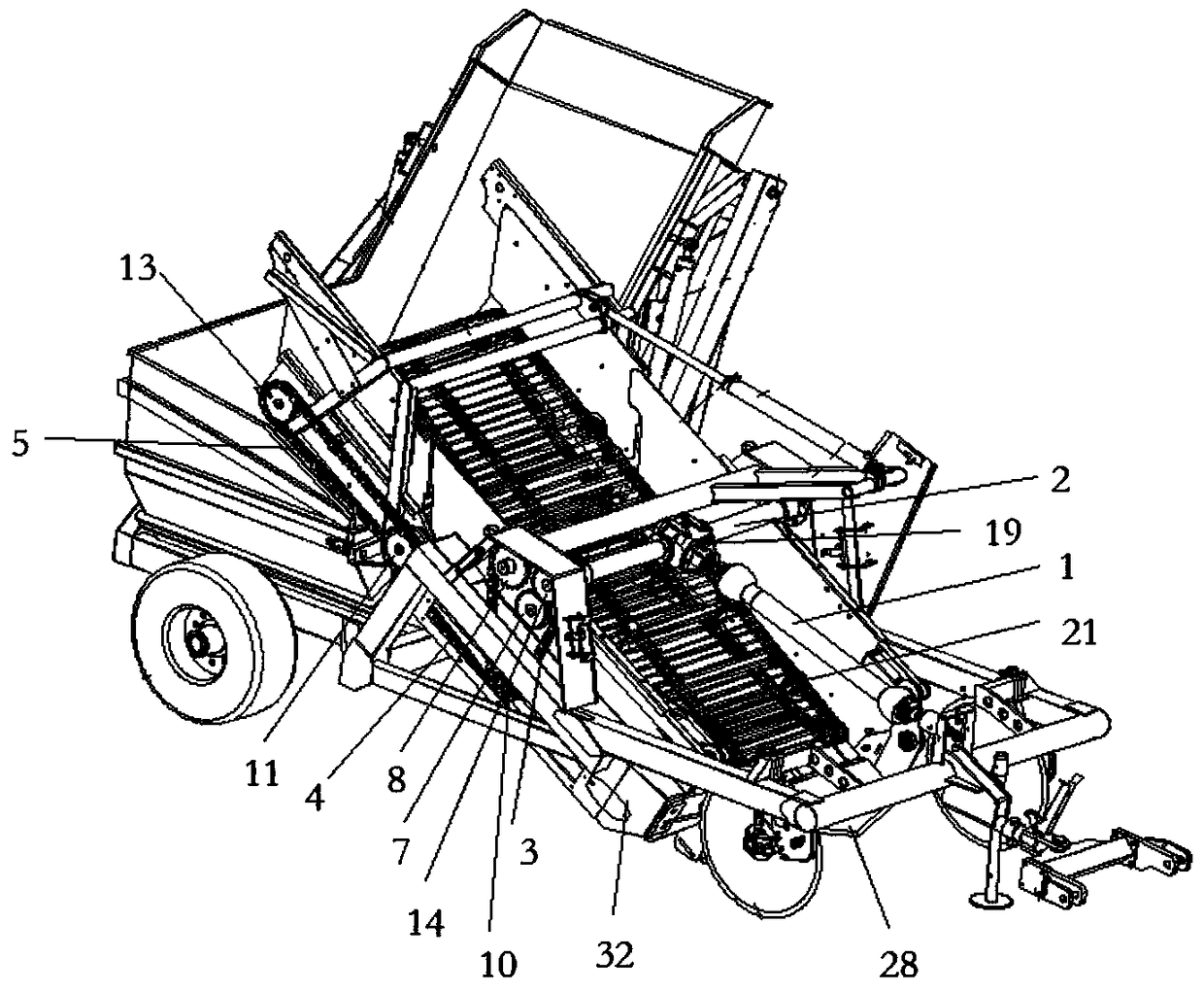
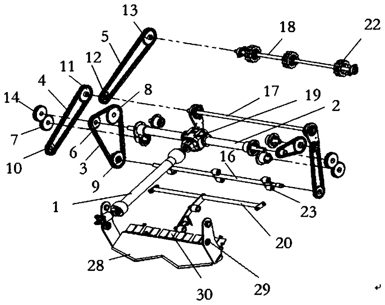
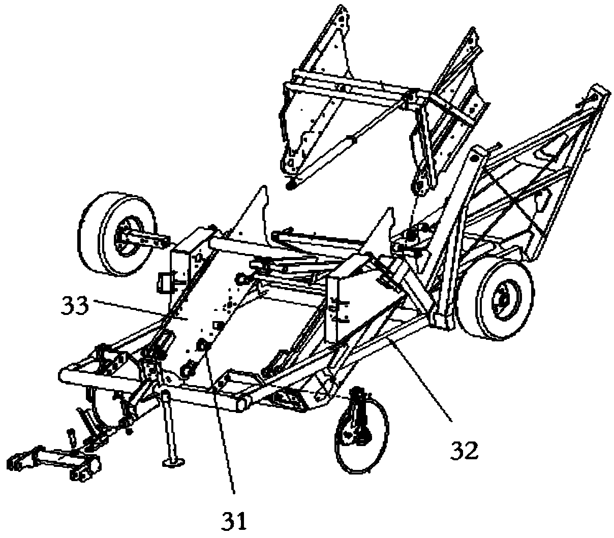
[0027] Such as Figures 1 to 8 Shown, a kind of cassava harvester transmission mechanism comprises transmission universal joint 1, universal joint transmission shaft 2, first transmission chain 3, second transmission chain 4, the third transmission chain 5, first transmission sprocket 6, The second transmission gear 7, the third transmission sprocket 8, the fourth transmission sprocket 9, the fifth transmission sprocket 10, the sixth transmission sprocket 11, the seventh transmission sprocket 12, the eighth transmission sprocket 13, the ninth transmission sprocket Transmission gear 14, primary conveying vibration shaft 16, secondary conveying rotating shaft 17, tertiary conveying rotating shaft 18 and swing rod 26, the first transmission sprocket 6 and the ninth transmission gear 14 are respectively installed on the universal The two...


PUM


Abstract

The invention discloses a transmission mechanism of a cassava harvester. The transmission mechanism comprises a transmission universal joint, a universal joint transmission shaft, a first transmissionchain, a second transmission chain, a third transmission chain and transmission chain wheels. The transmission chain wheels are correspondingly mounted with the various transmission chains, the firsttransmission chain wheel and a ninth transmission gear are mounted at two ends of the universal joint transmission shaft, a second transmission gear is mounted on a rotary shaft, the third transmission chain wheel is mounted on a shaft of a framework, the fourth transmission chain wheel and the fifth transmission chain wheel are mounted at two ends of a primary conveying vibrating shaft, the sixth transmission chain wheel and the seventh transmission chain wheel are mounted on a secondary conveying rotary shaft, and the eighth transmission chain wheel is mounted at two ends of a tertiary conveying rotary shaft. The transmission mechanism has the advantages that the integral transmission mechanism can be driven by a single power source to be operated and can stably and uniformly run, effects of driving digging shovels to carry out vibration type digging and driving conveying sieves to carry out vibration material conveying can be realized by the transmission mechanism, energy consumption can be reduced to a great extent, the work efficiency can be improved, and the like.

Description

technical field [0001] The invention relates to a cassava harvester, in particular to a cassava harvester transmission mechanism. Background technique [0002] The existing cassava harvester transmission mechanism is usually composed of vibration parts, excavation shovel transmission parts and conveying screen transmission parts. Due to unreasonable design, there are also defects in the following aspects: [0003] 1. The vibrating parts, excavating shovel driving parts and conveying screen driving parts are respectively driven by their own power sources. This operation mode of driving separately and driving one by one has a complex structure and a huge body, which leads to excessive energy consumption and is not easy to operate. operation, etc.; [0004] 2. At the same time, it drives the operation of each component by using the transmission chain on one side to drive the sprocket to run, but it is impossible to maintain a stable and uniform effect during the operation proc...

Claims


Application Information

Patent Timeline
IPC IPC(8): A01D13/00A01D17/08A01D33/12A01D33/08
CPCA01D13/00A01D17/08A01D33/08A01D33/12Y02P60/14
Inventor 吴洪珠邓干然李国杰周围郑爽崔振德李玲何冯光
Owner QINGDAO HONGZHU AGRI MACHINERY
Learn More