
Axial adjustable diaphragm coupler
A diaphragm coupling and axial technology, which is applied in the direction of couplings, elastic couplings, mechanical equipment, etc., can solve the problems of affecting the smooth operation of the coupling and the high processing cost of the spline shaft sleeve connection, and achieves Improve axial installation accuracy, improve safety, and have good structural effects
- Summary
- Abstract
- Description
- Claims
- Application Information
AI Technical Summary
Problems solved by technology
Method used
Image

Examples
Embodiment Construction
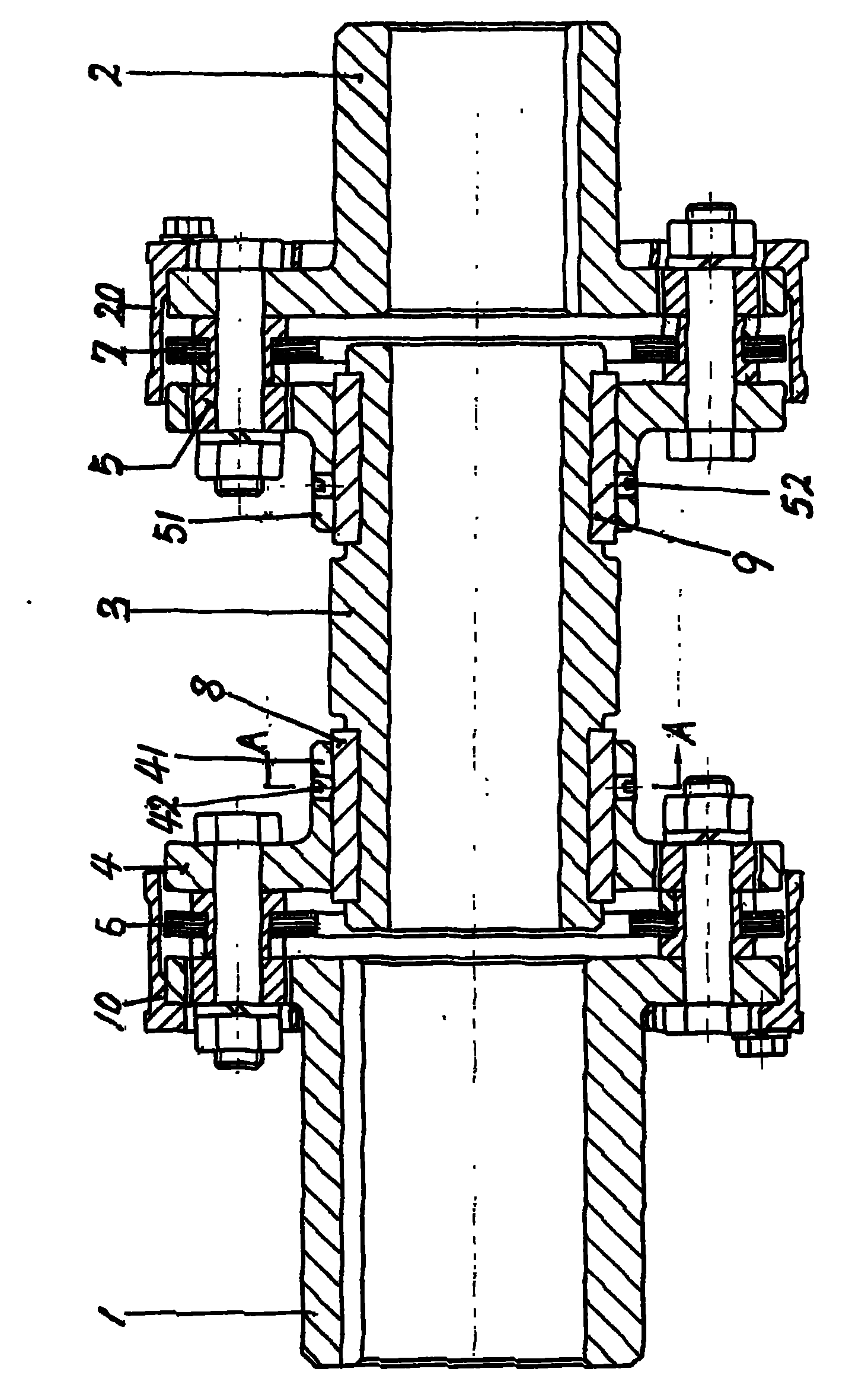
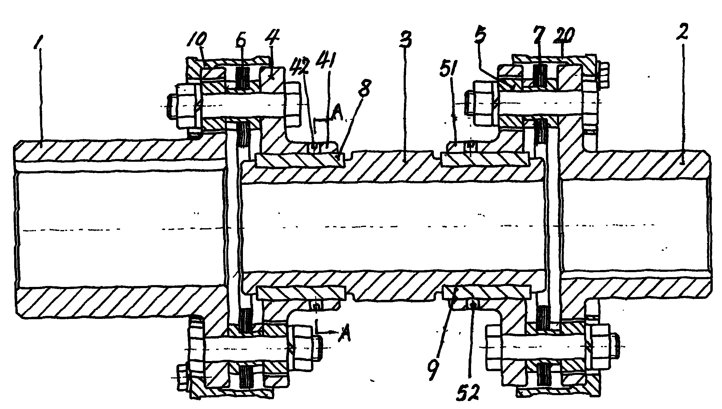
[0012] The present invention consists of driving end half shaft section 1, driven end half shaft section 2, intermediate shaft section 3, driving end intermediate shaft section flange 4, driven and driven end intermediate shaft section flange 5, driving end diaphragm assembly 6, slave The moving end diaphragm assembly 7 is composed of the driving end intermediate shaft joint flange 4 and the driven driven end intermediate shaft joint flange 5 through their bushings 41, 51 to cooperate with the outer circular flat keys at the left and right ends of the intermediate shaft joint 3 respectively.
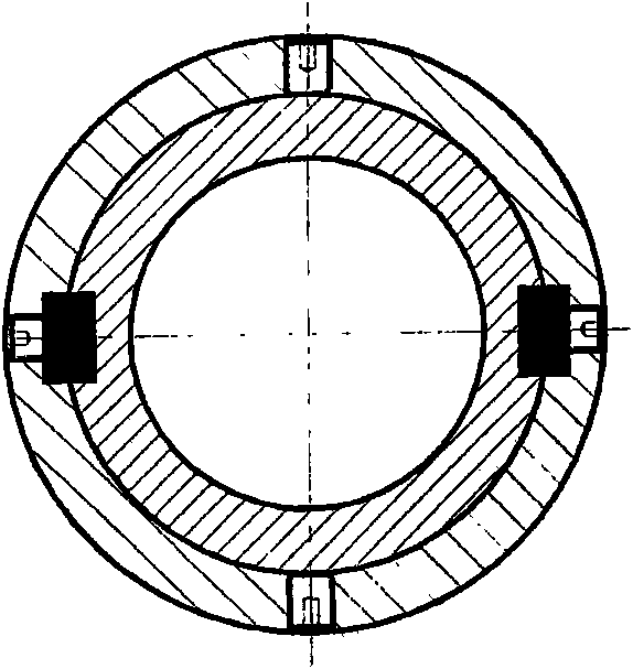
[0013] The sleeve parts 41 and 51 of the intermediate shaft section flange 4 at the driving end and the intermediate shaft section flange 5 at the driven end are interference fit with the outer circles of the left and right ends of the intermediate shaft section 3 respectively.
[0014] attached figure 1 As shown in the embodiment, the bushings 41, 51 of the intermediate shaft joint flan...
PUM
 Abstract
Description
Claims
Application Information