
Visualized data centre dispatching method and system

A technology of data centers and scheduling methods, applied in resource allocation, multi-programming devices, etc.

Inactive Publication Date: 2012-09-05
BEIHANG UNIV
View PDF3 Cites 0 Cited by
  • Summary
  • Abstract
  • Description
  • Claims
  • Application Information

AI Technical Summary

Problems solved by technology

[0008]Second, general management operations require operation time, such as the time required to turn on / off the physical server, improper management operations may also cause the application to violate its own services Service-Level Agreement (SLA)
Assume that the data center has just shut down a server according to the lower workload demand in the previous stage, but the workload in the next stage has increased significantly, and it will take a certain amount of time to restart the server, which cannot serve the workload in time

Method used


Image

  • Visualized data centre dispatching method and system
  • Visualized data centre dispatching method and system
  • Visualized data centre dispatching method and system

Examples


Embodiment 1

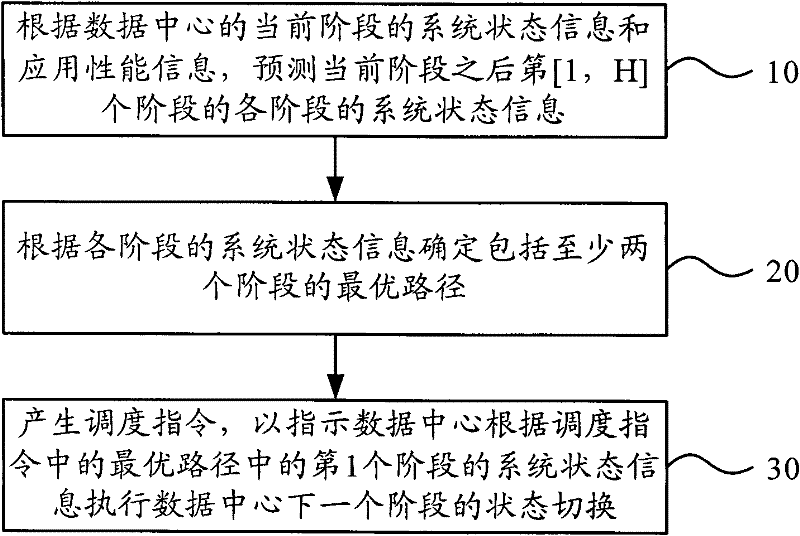
[0057] figure 2 It is a flow chart of the virtualized data center scheduling method provided by Embodiment 1 of the present invention, as shown in figure 2 As shown, in this embodiment, the virtualized data center scheduling method includes:

[0058] Step 10. According to the system state information and application performance information of the current stage of the data center, predict the system state information of each stage in the [1, H] stage after the current stage, where H is a natural number, and H>1;

[0059] Step 20, determining an optimal path including at least two stages according to the system status information of each stage;

[0060] Step 30, generating a scheduling instruction to instruct the data center to perform state switching of the next stage of the data center according to the system state information of the first stage in the optimal path in the scheduling instruction.

[0061] The technical solution of this embodiment finds the optimal path by p...

Embodiment 2

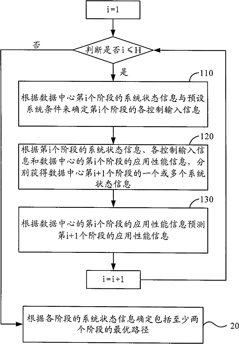
[0064] image 3 The flow chart of the method for predicting system status information provided by Embodiment 2 of the present invention is shown in FIG. 3 . The virtualized data center scheduling method provided by Embodiment 2 is based on Embodiment 1. If the current The stage is the first stage, and step 10 can be implemented specifically in the following ways.

[0065] Step 110: Determine each control input information of the i-th stage according to the system status information and preset system conditions of the i-th stage of the data center;

[0066] Step 120, according to the system state information of the i-th stage, each control input information and the application performance information of the i-th stage of the data center, respectively obtain one or more system state information of the i+1th stage of the data center;

[0067] Step 130. Predict the application performance information of the i+1th stage according to the application performance information of the i...

Embodiment 3

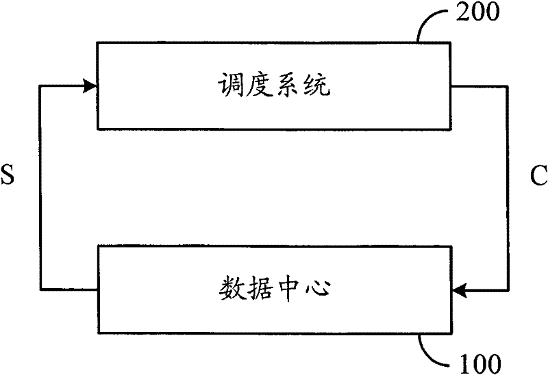
[0074] Figure 5 A schematic structural diagram of a virtualized data center scheduling system provided in Embodiment 3 of the present invention, as shown in Figure 5 As shown, the virtualized data center scheduling system can apply the virtualized data center scheduling method provided by the present invention, but it is not limited thereto. The virtualized data center scheduling system includes a scheduling module 50. The scheduling module 50 includes a system state prediction module 510, a system state optimization module 520, and a scheduling instruction generation module 530. The system state prediction module 510 is used to predict the system state according to the current stage of the data center. The system state of each stage of the [1, H] stage after the current stage, wherein H is a natural number, and H>1; the system state optimization module 520 is used to determine the optimal state including at least two stages according to the system state information of each ...


PUM


Abstract

The invention provides a visualized data centre dispatching method and system. The method comprises the following steps: according to the system state information and the application performance information of the current stage of the data centre, predicting the system state information of each stage of the [1,H]th stage after the current stage, wherein H is a natural number and is greater than 1; according to the system state information of each stage, determining the optimal path comprising at least two stages; and generating a dispatching order to indicate the date centre to perform the state switching of the next stage of the data centre according to the system state information of the first stage in the optimal path in the dispatching order. The system comprises a dispatching module which comprises a system state prediction module, a system state optimization module and a dispatching order generation module. The visualized data centre dispatching method and system provided by theinvention determine the system state of the next stage by predicting the system state information of several stages after the current stage, thus avoiding wasting resource due to frequent operation.

Description

technical field [0001] The present invention relates to data center scheduling technology, in particular to a virtualized data center scheduling method and system. Background technique [0002] A data center refers to a distributed computing system composed of multiple heterogeneous servers connected by a network to carry enterprise-level applications that provide online services. In the data center, centralized and unified management of a large number of servers can ensure the stable power supply environment required for server operation, suitable temperature and humidity control and network bandwidth conditions. [0003] Traditional server application deployment often adopts a dedicated server (Dedicated server) method. In this method, generally a physical node only deploys a single application or a component of an application to avoid multiple applications deployed on the same physical node. affect each other. However, this method will inevitably lead to low utilization...

Claims


Application Information

Patent Timeline
Patent Type & Authority Patents(China)
IPC IPC(8): G06F9/50
Inventor 沃天宇胡春明衣敏李博
Owner BEIHANG UNIV
Learn More